Injection molding is a necessity of modern manufacturing. It’s fast, efficient, and produces incredibly consistent, high-quality parts. But let’s be honest: even for seasoned professionals, the process can sometimes be difficult between man, machine, and material.
When something goes wrong, it doesn’t just affect a single part—it can lead to massive scrap rates, costly downtime, and missed deadlines. The key to success lies in quickly diagnosing the problem and implementing the right solution.
Today, we’re breaking down the most common injection molding defects, why they happen, and how you can fix them.
SINK MARKS
What they look like: Small craters or depressions on the surface of a thicker section of the part, like a rib or boss.
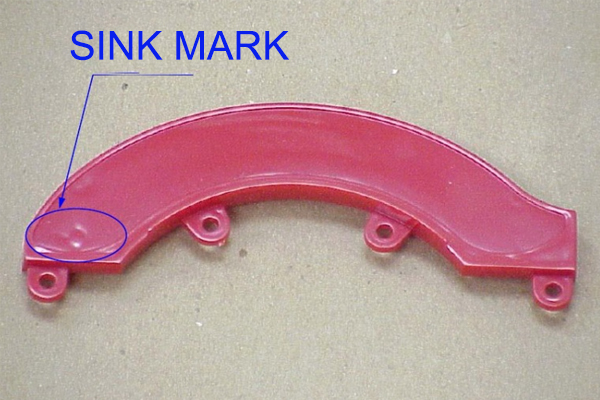
The Root Cause: Sink marks occur when the inner part of a thick section cools and shrinks faster than the outer surface, pulling the surface inward. This is fundamentally a cooling issue, often linked to insufficient packing pressure or time.
Solutions:
Increase Packing Pressure & Time: This forces more material into the mold to compensate for shrinkage.
Adjust Cooling Time: Extend the cooling time to allow the entire cross-section to solidify uniformly.
Redesign the Part: The best solution is often preventive. Design parts with uniform wall thickness. If a thick boss is necessary, use a coring design to reduce mass.
Check Material: Some materials shrink more than others. Ensure the material is appropriate for the part geometry.
FLASH
What it looks like: Thin, excess material that seeps out along the parting line or around ejector pins, creating a thin “fin” or “burr.”
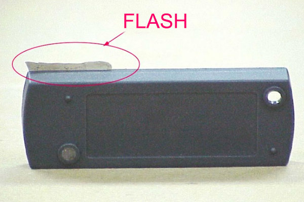
The Root Cause: Flash happens when the mold clamp force is not enough to keep the mold closed against the immense injection pressure. It can also be caused by mold wear, damage, or contamination preventing a proper seal.
Solutions:
Increase Clamp Tonnage: Ensure the machine has enough power to keep the mold tightly closed.
Reduce Injection Speed/Pressure: Lower the force pushing the material into the cavity.
Inspect and Maintain the Mold: Check for damage, wear, or debris on the parting lines, vents, and ejector pins. Proper mold maintenance is crucial.
SHORT SHOTS
What they look like: The molten plastic fails to completely fill the mold cavity, resulting in a missing section of the part.
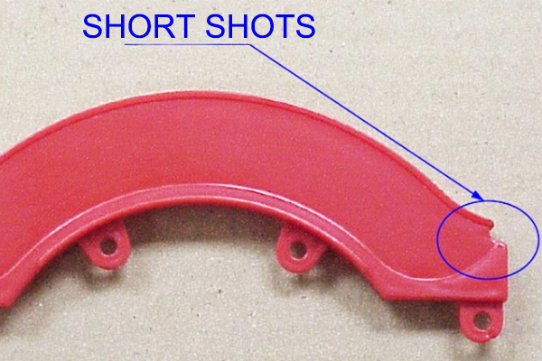
The Root Cause: Simply put, not enough material made it into the mold. This can be due to:
Insufficient material feed (e.g., a blocked hopper)
Venting problems (trapped air prevents plastic flow)
Low melt temperature (plastic is too viscous to flow)
The injection speed/pressure is too low
Solutions:
Increase Injection Pressure/Speed: Helps push the material further into the cavity.
Raise Melt and Mold Temperature: A hotter material flows more easily.
Check for Vent Blockages: Ensure vents are clear to allow air to escape.
Verify Material Feed: Ensure the hopper is full and the feed throat is not blocked.
WARPING
What it looks like: A part that twists, bends, or bows out of its intended shape after ejection.
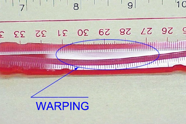
The Root Cause: Uneven cooling. When one part of the component cools and solidifies faster than another, internal stresses are created that pull the part out of shape.
Solutions:
Optimize Cooling System Design: Ensure cooling channels are placed to promote uniform cooling.
Lower Mold Temperature: A slower, more uniform cooling cycle can reduce stress.
Adjust Packing Pressure: Too high a pressure can create uneven internal stress.
Use a Material with Lower Shrinkage: Some filled materials (e.g., glass-filled) warp less.
WELD LINES
What they look like: A visible line or notch on the surface where two flow fronts meet but don’t properly unite.
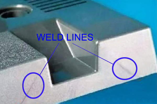
The Root Cause: Inevitable in parts with holes or multiple gates, as the plastic flow splits and rejoins. They are weak points and can be visually apparent if the flow fronts have cooled too much before meeting.
Solutions:
Increase Melt/Mold Temperature: This keeps the plastic fluid for longer, allowing the fronts to blend better.
Increase Injection Speed: Gets the flow fronts to meet before they start cooling.
Relocate Gates: Changing the gate location can change where the weld lines form, moving them to a less critical area.
Improve Venting: Trapped air at the meeting point can worsen weld lines.
BURN MARKS
What they look like: Black or brown discolorations on the edge or surface of the part.
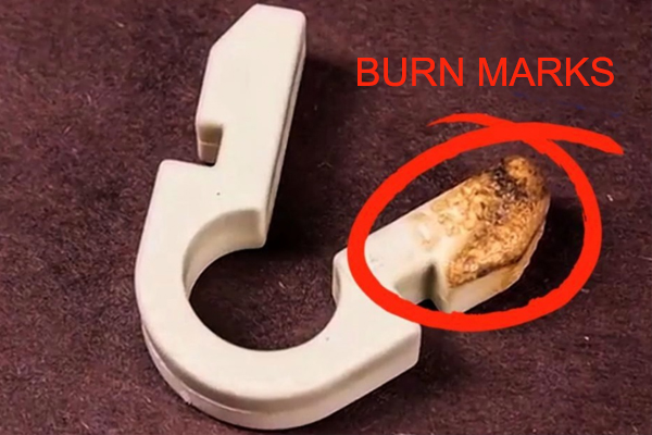
The Root Cause: Typically caused by trapped air that gets superheated and literally burns the plastic. It can also be caused by overheating the material in the barrel.
Solutions:
Reduce Injection Speed: Slower injection allows air to escape through vents instead of getting trapped and compressed.
Improve Mold Venting: Add or clean vents, especially in areas where air is likely to be trapped.
Lower Melt Temperature: Prevents degrading the polymer in the barrel.
Check for Over-Packing: Can cause excessive shear heat, which burns the material.
Quick-Reference Troubleshooting Table
| Defect | Likely Cause | Quick Fix |
| Sink Marks | Insufficient packing, thick walls | Increase pack pressure/time, improve cooling |
| Flash | Low clamp force, mold damage | Increase tonnage, clean/repair mold |
| Short Shot | Low pressure/speed, cold material | Increase pressure/speed, raise temperatures |
| Warping | Uneven cooling | Optimize cooling system, lower mold temp |
| Weld Lines | Flow fronts meeting | Raise temp/speed, relocate gate |
| Burn Marks | Trapped air, high temp | Improve venting, reduce speed & temp |
The Best Solution: Prevention
While this guide is a great starting point, the most effective troubleshooting tool is a well-designed process from the start. This includes:
-
Design for Manufacturability (DFM): Designing parts with uniform walls and appropriate draft angles.
-
Preventive Maintenance: Regularly cleaning and inspecting molds.
-
Process Documentation: Keeping meticulous records of successful machine settings (a “golden shot”) for each job.
Understanding the “why” behind these common defects empowers you to not just fix problems, but to prevent them altogether.