
Why Plastic Part Dimensions Change After Molding — A Real Case
Last year we made a helical gear in POM for a European customer. Nominal pitch diameter: 32.85 mm, tolerance ±0.03 mm. T1 samples came off the tool, we conditioned them, measured them on our CMM about 48 hours after molding, and every critical dimension was within spec. We signed the FAI, shipped the parts, and waited for approval.
Instead we got a report: three dimensions out of tolerance by 0.05 mm. Same parts. Same batch. Nobody had touched the tool.
What had changed was time. Our CMM saw the part at hour 48. Theirs saw it several days later, after transit and warehouse storage, after more post-molding shrinkage and more crystallisation had taken place. Both measurements were honest. Both were right for the moment they were taken. And they still disagreed by more than the tolerance allowed.
That project cost us a round trip of tool correction and three weeks. It also taught us the rule we now put on every drawing note for critical parts: a tolerance without a measurement window is not a tolerance — it’s an argument waiting to happen.
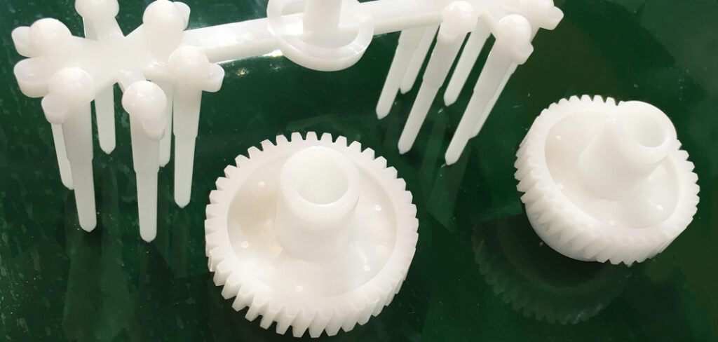
Why POM Is the Worst Case for This
POM is one of the materials where this problem bites hardest, for two reasons:
It’s semi-crystalline. Crystallisation doesn’t finish at ejection. The part continues to densify and contract over hours to days, especially in thicker sections.
It isn’t moisture-driven. Unlike PA6 or PA66, POM absorbs very little water, so you can’t explain the drift away as humidity conditioning. In this case, the drift was almost entirely post-molding shrinkage plus temperature.
And gears amplify everything: a small change in bore or pitch diameter changes centre distance and mesh quality — which is exactly what the customer was checking, with a gear tester rather than our CMM. So there was a second mismatch hiding in the same dispute: we weren’t measuring the same thing, in the same way, at the same time.
The Four Things That Move a Part After Ejection
- Post-molding shrinkage and stress relaxation.
Molten plastic is frozen into shape under pressure. Once released, internal stresses relax and the part continues to contract. Semi-crystalline resins — PA, POM, PP, PBT — do this most, because crystallisation continues after ejection.
- Moisture uptake.
This is the dominant mechanism for PA6/PA66, PC and PBT: absorbed water plasticises the matrix and increases dimensions, sometimes reversing the direction of drift. It wasn’t the driver in our POM case, but it is why a part can drift one way and then back the other — and why “we measured it in spec” means nothing unless the moisture state is agreed.
- Measurement temperature.
Plastics expand on the order of tens to roughly one hundred ppm per °C. On a medium-sized feature, a ten-degree difference between the shop floor and the metrology room can easily reach a few hundredths of a millimetre — larger than many tight tolerances. Measuring warm parts straight off the machine is measuring something else entirely. In our case the parts also sat in a container and a warehouse at uncontrolled temperature before the customer ever touched them.
- Orientation and warpage over time.
Flow-induced anisotropy creates uneven internal stress. Flatness and bow can develop over hours to days, especially on thin, large or asymmetric features.
Why Standards Build Acceptance Conditions In
This is exactly why ISO 20457 writes acceptance conditions into the standard instead of leaving them to custom: conditioning, ambient conditions and measurement method are part of acceptance, not an optional detail. The long-standing convention is measurement in a standard atmosphere (23 °C / 50 % RH) with a minimum conditioning time after molding.
If supplier and customer measure at different times, temperatures or with different fixtures, both can be correct and still disagree. That’s a process failure, not a mold failure — and the agreed acceptance conditions decide who is right. In the gear case we had no agreed conditions at all, so there was nothing to decide against.
For the full framework — TG grades, W/NW dimensions, and how the grade is derived — see our guide:
What to Put on the Drawing
Agree on these four things in writing before the first shot:
- The measurement window — both ends of it. Not just “after 16 h minimum,” but also a maximum: measured at 23 ± 2 °C / 50 ± 10 % RH, between [16 h] and [72 h] after molding, so both sides measure the same material state. This single line would have prevented the gear problem.
- The method. CMM vs dedicated fixture vs functional gauge, datum scheme, clamping force, probe strategy. For gears, specify whether the check is dimensional (bore, pitch diameter) or functional (mesh, centre distance).
- The drift characterisation. Measure the same samples at 24 h / 48 h / 72 h and record the delta. This turns an unknown into a number you can design against.
- The tolerance allowance. Build the measured drift into the tolerance band or into the mold compensation, rather than discovering it at FAI.
Reducing the Drift Itself
- Control hold pressure and hold time — under-packed parts move more.
- Balance wall thickness and gate position to reduce orientation-driven warpage.
- Stabilise mold temperature and use consistent cooling; tight control matters most on critical parts.
- Consider annealing or extended conditioning for dimensionally critical parts.
- Choose lower-shrinkage resins where function allows — though with a gear in POM that’s usually not an option, which is exactly why the measurement window matters more.
What We Do on Every Project
For dimensionally critical features, we run a 24/48 h dimensional record on T1 samples and, before tool correction, agree on the measurement window with the TONGDA LINK quality and engineering teams.
FAQ
Most likely post-molding shrinkage and continued crystallisation, compounded by different measurement times and temperatures. For POM, humidity is rarely the explanation; for PA6/PA66 it often is.
Common practice is a minimum of 16 hours at 23 ± 2 °C / 50 ± 10 % RH. But a minimum alone isn’t enough — add a maximum window (e.g. within 72 h) so supplier and customer measure the same material state.
Not necessarily. It’s usually material behaviour plus unmatched measurement conditions. It only becomes a real problem when the drift exceeds the allowance built into the tolerance.
Measure the same samples at 24, 48 and 72 hours and record the deltas; use that data to set the tolerance band or mold compensation. That’s the single most useful piece of data you can get from a T1.
It applies to all moulded plastics, but the dominant mechanism differs: semi-crystalline resins drift mainly through continued crystallisation; hygroscopic resins (PA, PC, PBT) drift mainly through moisture uptake; amorphous resins drift least but still shift with temperature and stress relaxation.