
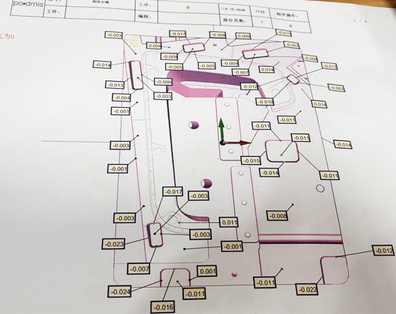
In the precision plastic injection molding, few specifications carry as much weight as dimensional tolerance. When an engineer specifies ±0.005mm on a drawing, they are demanding a level of precision that separates capable mold makers from the rest of the industry.
When a customer sends us a drawing with ±0.005mm on a handful of dimensions and asks a simple question: “Can you hold this?”
At TONGDA LINK, our answer is never just yes or no. It’s: which dimensions, in what material, at what volume, and measured under what conditions.
That’s not hedging. It’s the only honest way to talk about precision. Because ±0.005mm means two very different things depending on whether you’re measuring steel or plastic—and confusing the two is how tooling projects burn time and budget.
This guide walks through what the number really means, where it’s achievable, where it isn’t, and how we approach it on our own floor. If you’re evaluating a supplier (us included), you can use it as a checklist.
The Distinction That Changes Everything: Mold vs. Plastic Part
The first thing we clarify on every RFQ is this:
| Mold Machining Accuracy | Molded Part Tolerance | |
|---|---|---|
| What’s measured | Cavity/core dimensions in the steel | The finished plastic dimension |
| Realistic range | ±0.003 – ±0.005mm routinely achievable on precision machines | ±0.01 – ±0.02mm for high-precision work; ±0.005mm only on small, stable features under tight control |
| Main variables | Machine accuracy, thermal drift, electrode wear | Shrinkage, thermal expansion, moisture, warpage, process drift over thousands of cycles |
| Who controls it | The toolmaker | The toolmaker, the molder, the material, and the room it’s measured in |
The mold is cut from metal and measured once. The part is formed from a material that shrinks as it cools, keeps shrinking for 24–48 hours after ejection, expands with temperature, and—in semi-crystalline resins—shrinks differently along the flow direction than across it.
So when a supplier promises “±0.005mm on all dimensions,” treat it as a question, not an answer. A partner worth working with will tell you which features can hold it and which can’t—before quoting, not after T1.
That said: sub-0.005mm work on mold steel is achievable on a properly equipped, thermally stable machine. It’s the foundation everything else rests on. Here’s how we build it.
Where ±0.005mm Sits in the Tolerance Hierarchy
| Grade | Typical Range | Typical Applications |
|---|---|---|
| Commercial | ±0.25 – ±0.50mm | Consumer goods, packaging, non-critical housings |
| Fine | ±0.10 – ±0.25mm | General engineering parts, appliance components |
| Precision | ±0.05 – ±0.10mm | Automotive trim, electronic housings |
| High Precision | ±0.01 – ±0.05mm | Connector pins, sensor housings, medical components |
| Ultra Precision | ±0.005mm and below | Precision connectors, optical components, micro-molding, critical tooling features |
To feel what 0.005mm means: a human hair is roughly 0.07mm—seven times wider than the whole tolerance band. A sheet of paper is about 0.1mm thick—ten times the range.
And here’s the one that catches people out: polypropylene expands at roughly 100–150 ppm/°C. On a 30mm PP part, a 3°C difference between your measuring room and ours changes the length by about 0.01mm—the entire tolerance band, gone to temperature.
That’s why any ±0.005mm claim has to state the measurement temperature. If it doesn’t, the number isn’t verifiable.
Why Plastic Parts Drift: The Four Variables
We see these four variables on nearly every tight-tolerance project. Knowing them helps you judge a drawing before any steel is cut.
1. Shrinkage is a range, not a constant. ABS shrinks 0.4–0.7%. PC 0.5–0.7%. POM 1.8–2.5%. PEEK 1.0–1.5%. PP 1.0–2.5%.
On a 10mm ABS dimension at 0.5%, the cavity gets cut to 10.05mm. If actual shrinkage misses the prediction by 0.1%, the part shifts 0.01mm—already the full ±0.005mm band. That’s why we don’t rely on generic shrinkage tables; we run mold-flow analysis calibrated to the actual resin lot and gate layout.
2. Anisotropic shrinkage. Glass-filled resins shrink less overall but differently in flow vs. cross-flow direction. Round holes go slightly oval; long dimensions bow. You can compensate for it—but only with data from the actual tool.
3. Measurement temperature. Plastics expand 5–10× more than steel per degree. A dimension measured at 30°C is not the same dimension at 20°C. We record the ambient temperature on all critical inspection reports for this reason.
4. Post-molding change. Nylon absorbs moisture and grows. Stress relaxes. Crystallization continues. A part measured at 2 hours can read differently at 48 hours. We agree on conditioning time with the customer up front so first-article data is comparable.
How We Build It: The Chain at TONGDA LINK
Precision is a chain. One weak link and the number on the drawing doesn’t matter.
Design & compensation. Shrinkage compensation goes into the CAD model before any toolpath is written, based on mold-flow results rather than rule of thumb.
Need Manufacturing Precision Molds and Plastic Injection Molded Parts
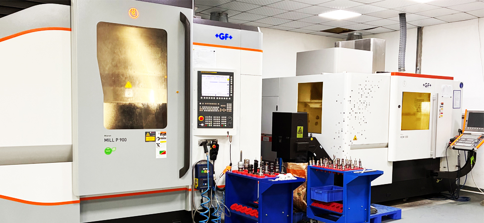
CNC machining. Cavities and cores are cut tighter than the part tolerance. TONGDA LINK CNC machines are MIKRON MILL P 900, MIKRON HEM 1000, Beijing Jingdiao CNC. We machine on MIKRON high-speed machining centers—cast-iron structure with a circulating coolant pad between the main motor and spindle head to block heat transfer, and a closed internal cooling system that keeps the spindle head temperature constant. At this level of tolerance, heat is the enemy, not the cutting tool. Finishing is done in a single setup wherever possible to eliminate re-clamping error, with positional feedback verified on each setup.
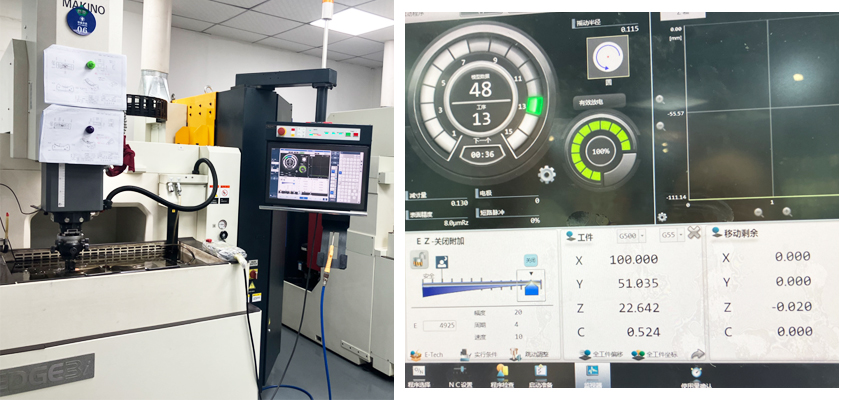
Fine-finish EDM. Final cavity surfaces are produced on Makino EDGE3i mirror-finish sinker EDM. The machine uses a fixed-table design with the oil tank integrated into the base casting for thermal stability, and SuperSurface/SuperEdge generator technology to produce uniform, pinhole-free surfaces. Multiple passes (rough → semi → finish) with programmed electrode wear compensation; target cavity finishes in the Ra 0.1–0.4μm range. For narrow-pitch connector cores, corner radii are held at the single-digit micron level—this is where connector mold precision is actually won or lost.
Assembly & fitting. Parting-line alignment, ejector clearances, interlocks lapped to zero gap, guide pins matched with minimal clearance. Perfectly machined halves assembled carelessly still make bad parts.
Process control. On a precision job we hold melt temperature within ±2°C, injection pressure consistency within ±1%, cooling time within ±0.5s, and cavity temperature uniformity within ±2°C.
Verification. We verify critical dimensions on a Hexagon DEA CROMA bridge-type CNC CMM (MPE in the 0.005mm range), temperature-compensated and calibrated with traceable certificates—because a report is only as good as the machine that produced it. Inspection is carried out in a controlled room, and parts are allowed to stabilize after molding before measurement so that first-article data is repeatable.
One principle we apply consistently: the gauge must be appropriate to the tolerance. For ultra-tight features where the tolerance band approaches the capability of a shop-floor CMM, we don’t pretend a report proves what it can’t. Instead we agree the measurement method with the customer up front—using functional gauges, calibrated masters, optical/vision systems, or third-party high-accuracy metrology—and we state it explicitly in the inspection plan. If a supplier hands you a CMM report claiming to prove ±0.005mm on a plastic part, ask what machine was used and what its MPE is. The answer will tell you more than the numbers in the table.
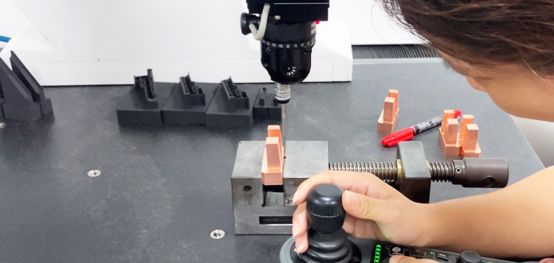
Inspection room: parts stabilized before measurement.
What We Will—and Won’t—Promise
We’d rather lose a quote than win it with a promise we can’t keep. So here’s our honest line:
- On the mold steel: sub-0.005mm work is achievable on properly equipped machines, and we verify it with CMM data and share the report.
- On small, critical part features (pins, bores, sealing lands, insert pockets, 1–5mm): achievable with the right material and process, and proven with Cpk data over a run.
- Across a full parting line or on a large envelope dimension (30mm+): we’ll usually recommend tolerancing the critical local feature instead of the overall length. It costs less, yields better, and still gives you the fit you need.
- On high-shrink materials (PP, PE, TPE) at ±0.005mm: we’ll tell you up front if the material is fighting the tolerance.
If a supplier agrees to everything without a single pushback, ask yourself why. The most valuable thing a tooling partner can give you is a DFM report that flags risk early—when changes are cheap.
Proof You Can Check Yourself
Don’t take “high precision” as a claim. Ask for these five things. Any competent supplier can produce them; a weak one can’t.
- A DFM response that names the at-risk dimensions and proposes a fix, rather than repeating your tolerance back to you.
- CMM reports from a comparable completed project, showing actual measured values—not just “OK” stamps.
- Cpk data on a similar feature over a sustained run, not the first 30 shots off a freshly tuned machine.
- An equipment list with brands and the calibration status of the measuring equipment (check the sticker dates).
- A mold trial video and sample parts, so you can see finish, gating, and ejection for yourself.
For reference, professional buyers anchor these discussions in DIN 16901 (plastics mouldings — tolerances) or ISO 20457 (plastics moulded parts — tolerances and acceptance conditions). Citing a standard grade instead of applying ±0.005mm everywhere gets you more realistic quotes and fewer arguments at FAI.
How to Write Tolerances That Don’t Create Disputes
- Use GD&T. Control form, orientation, and location alongside size. A hole at ±0.005mm means little if its position can float 0.1mm.
- Tighten selectively. Only the dimensions governing fit, function, or assembly need ultra precision. Over-specifying raises cost exponentially and lowers yield.
- State measurement conditions. Equipment type, datum scheme, temperature, and conditioning time (e.g., “23±2°C after 48h”).
- Define the sampling plan. How many parts, how often.
- Cite a standard. DIN 16901 or ISO 20457 gives both sides an objective baseline.
±0.005mm isn’t just a number—it’s a statement about the capability of an entire system. On mold steel, sub-0.005mm work is achievable on a properly equipped, thermally stable machine, and must be verified by a method appropriate to the tolerance. On a molded plastic part, that level of control is achievable only on selected features, with the right material, under controlled conditions, and maintained with statistical process control.
Specify it selectively. Verify it with data. And choose a partner who tells you where the limit is before cutting steel, not after.
At TONGDA LINK, that’s how we prefer to work: clear on what we can guarantee, honest about what we can’t, and documented either way.
Want Us to Review Your Drawing And Make A Quotation/DFM Report?
Send us your 3D model, and we’ll return a quotation within 2 working days, marking each critical dimension as achievable / achievable with compensation / not recommended—with alternatives and the reasoning behind each call. No charge, no obligation.
Prefer to Self-Check First?
Ask for our Tolerance Capability Sheet—a one-page reference of achievable tolerance bands by material, feature size, and feature type.
Tolerance Capability SheetFAQ
±0.005mm is routinely achievable on the mold steel. On the molded plastic part, it is only realistic on small, stable features (1–5mm pins, bores, sealing lands) with low-shrink materials like PC, POM or PEEK, under controlled conditions and verified with appropriate metrology. Overall envelope dimensions of 30mm+ are typically held to ±0.01–0.02mm.
Mold accuracy refers to the machined cavity/core dimensions in steel, typically ±0.003–0.005mm. Part tolerance is the finished plastic dimension, affected by resin shrinkage, thermal expansion, moisture uptake and process drift. The mold is measured once in metal; the part changes after ejection.
Professional buyers cite DIN 16901 for plastics moulding tolerances or ISO 20457 for plastics moulded parts tolerances and inspection. Referencing a standard grade instead of applying ±0.005mm everywhere produces more realistic quotes and fewer disputes at first article inspection.
Cpk ≥ 1.33 indicates a capable process; Cpk ≥ 1.67 is typically required for automotive and medical applications. Cpk < 1.0 means the process cannot consistently hold the tolerance. Always ask for Cpk data over a sustained production run, not just the first shots off a tuned machine.