
When you send a 3D CAD model of your plastic part to a mold maker, the first document you should receive before any steel is cut is the DFM (Design for Manufacturability) report. This report is the mold maker’s professional assessment of whether your part design can be manufactured efficiently, economically, and to the required quality standards.
A DFM report is not just a formality—it is the single most important document in the mold development process. It identifies potential problems before they become expensive mistakes, suggests design modifications that can save weeks of lead time and thousands of dollars in rework, and establishes a shared understanding between you and your mold maker about how the part will be made. At TONGDA LINK, every DFM report we issue follows this exact structure — and we include it as a standard deliverable before any steel is ordered.
This guide teaches you how to read, interpret, and act on a DFM report, whether you are an experienced engineer or a first-time buyer working with a Chinese mold supplier. If you’re curious about what a professional DFM report looks like, get in touch with our team.
CONTACT TONGDA LINKWhat Is a DFM Report?
A DFM report is a structured technical document prepared by the mold maker’s engineering team after analyzing your 3D CAD model. It evaluates the part design against the practical constraints of injection molding and mold manufacturing, identifying features that may cause production problems and recommending modifications to improve manufacturability.
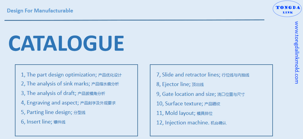
A comprehensive DFM report typically includes:
- Part geometry analysis(wall thickness, draft angles, undercuts, sink marks, surface texture)
- Material recommendations(shrinkage rate)
- Mold structure proposal(parting line, gate location and size, ejector pin layout, slider/lifter requirements, mold layout, engraving and aspect)
- Mold flow simulation results(fill pattern, weld lines, air traps, warpage prediction)
- Tolerance assessment
- Recommended design changes(with before/after visualizations)
- Estimated cycle time and production feasibility
- Injection machine
At TONGDA LINK, our DFM reports typically run 15–25 pages and include 3D renderings with color-coded analysis maps for every project. We don’t send a generic template — each report is tailored to your specific part geometry and material.
See What Our DFM Reports Look LikeSection-by-Section Guide to Reading a DFM Report
Section 1: Part Geometry Analysis
This section evaluates the basic geometry of your part against fundamental injection molding rules.
Wall Thickness
The report will show a color-coded wall thickness analysis map:
- Blue/green areas: Nominal wall thickness (ideal).
- Yellow areas: Slightly thick or thin (may need attention).
- Red areas: Significantly thick or thin (high risk of defects).
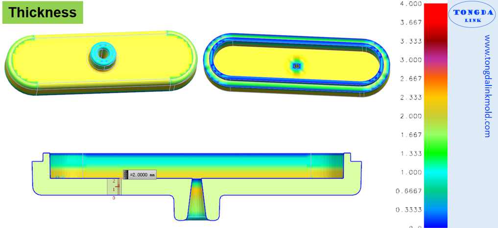
IMAGE 1: Sample wall thickness analysis color map from a TONGDA LINK DFM report
What to look for:
- Thick sections (>3-4mm for most materials): Risk of sink marks, voids, and extended cycle times. The report may suggest coring out thick sections or adding ribs.
- Thin sections (<0.5mm for most materials): Risk of short shots (incomplete filling) and high injection pressure requirements.
- Thickness transitions: Abrupt changes in wall thickness cause differential cooling and warpage. The report should recommend gradual transitions (3:1 ratio minimum).
Injection Molding: Wall Thickness Design Principles
Draft Angles
The report will flag any vertical or near-vertical surfaces that lack sufficient draft angle for ejection:
- Smooth surfaces: Minimum 0.5-1° draft.
- Textured surfaces: Minimum 1.5° per 0.025mm of texture depth.
- Shut-off surfaces: Minimum 3° to ensure reliable sealing.
If the report flags insufficient draft, it means the part may stick in the mold, require excessive ejection force, or suffer surface damage during ejection.
Draft Angle Design in Injection Molding: A Technical Guide on Geometric Optimization for Demolding
Undercuts
Any feature that prevents the part from being ejected in a straight pull direction is an undercut. The report will identify:
- External undercuts: Require side-action sliders (increases mold cost and complexity).
- Internal undercuts: Require lifters or collapsible cores (even more complex and expensive).
The report may suggest design modifications to eliminate undercuts, such as adding shut-off features, redesigning snap fits, or using pass-through holes.
Section 2: Material Recommendations
The DFM report should confirm or challenge your material selection based on:
- Application requirements: Mechanical strength, temperature resistance, chemical resistance, UV stability, flammability rating.
- Moldability: Flow length-to-thickness ratio, shrinkage rate, and processing temperature window.
- Cost optimization: The report may suggest an alternative grade that meets your requirements at lower cost.
If the report recommends a different material than what you specified, review the justification carefully. A good mold maker will explain the trade-offs clearly.
Section 3: Mold Structure Proposal
This is the heart of the DFM report. It defines how the mold will be built to produce your part.
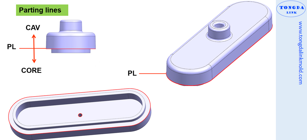
Parting Line Location
The parting line is where the two halves of the mold meet. Its location determines:
- Where flash (thin excess material) may appear on the part.
- Whether undercuts can be avoided.
- How the part will look cosmetically (the parting line is visible on the finished part).
The report should show the proposed parting line on a 3D rendering of your part. Review it carefully to ensure:
- The parting line is on a non-cosmetic edge or hidden feature.
- It does not cross critical sealing or mating surfaces.
- It allows for clean ejection without undercuts.
Gate Location and Type
The gate is the entry point where molten plastic enters the cavity. The report will specify:
- Gate type:Submarine gate, pin-point gate, fan gate, valve gate, hot runner gate, etc.
- Gate location:Where on the part the gate will be positioned.
- Gate vestige:The visible mark left after the gate is trimmed.
Types of Gates for Injection Molding
Review the proposed gate location for:
- Cosmetic impact: Gates leave marks. Ensure they are on non-visible surfaces.
- Flow balance: The gate should be positioned to fill the cavity evenly, minimizing weld lines and air traps.
- Pressure drop: Gates on thin sections may require excessive injection pressure.
Ejector Pin Layout
Ejector pins push the part out of the mold after cooling. The report should show:
- Pin locations: Distributed evenly to avoid concentrated stress.
- Pin marks: Small circular marks will appear on the part where pins contact. Ensure they are on non-cosmetic surfaces.
- Pin size: Larger pins leave larger marks but provide more ejection force.
Slider and Lifter Requirements
If your part has undercuts, the report will specify:
- Number of sliders/lifters: Each adds cost and complexity to the mold.
- Slider travel distance: Determines the mold size and machine tonnage required.
- Slider parting line: Where the slider meets the main parting line—this is a potential flash point.
Section 4: Mold Flow Simulation Results
A professional DFM report includes mold flow analysis using Moldflow (by Autodesk). This section is critical for predicting and preventing defects.
Fill Pattern
Shows how the molten plastic flows through the cavity:
- Balanced fill: All areas of the cavity fill simultaneously—ideal.
- Unbalanced fill: Some areas fill before others, causing differential packing and warpage.
Weld Lines (Knit Lines)
Where two flow fronts meet, a weld line forms. The report should show:
- Location: Are weld lines on cosmetic surfaces? (They should not be.)
- Strength: Weld lines are typically 20-50% weaker than the base material. Critical structural areas must be free of weld lines.
Air Traps
Areas where air cannot escape during filling. Air traps cause:
- Burn marks (diesel effect).
- Short shots (incomplete filling).
- Weak spots in the part.
The report should recommend vent locations or design changes to eliminate air traps.
Warpage Prediction
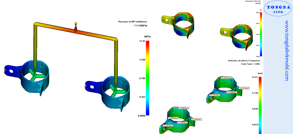
The simulation predicts how the part will deform after cooling and ejection:
- Color map: Shows the magnitude and direction of warpage.
- Critical areas: Identify zones where warpage exceeds your tolerance requirements.
- Recommendations: The report should suggest changes to wall thickness, cooling design, or process parameters to minimize warpage.
Pressure and Temperature Distribution
Shows the injection pressure required and the temperature distribution during filling:
- Peak injection pressure: Must be within the capability of available molding machines.
- Temperature uniformity: Large temperature differences indicate uneven cooling, which leads to warpage.
We run Moldflow simulations on every project and include the full simulation file with our DFM report so you can review it yourself.
Request a free Moldflow analysis for your part.
Section 5: Tolerance Assessment
The report should evaluate whether your specified tolerances are achievable given:
- The material’s shrinkage rate and variability.
- The part geometry and feature sizes.
- The proposed mold structure and manufacturing process.
If any tolerance is flagged as “at risk” or “not achievable,” the report should explain why and suggest alternatives (e.g., loosening the tolerance, changing the material, or adding a secondary machining operation).
Section 6: Recommended Design Changes
This is the action-oriented section of the DFM report. It should present:
- Before/after visualizations: Show the original design alongside the proposed modification.
- Priority ranking: Critical changes (must-fix) vs. recommended improvements (nice-to-have).
- Impact assessment: How each change affects mold cost, lead time, cycle time, and part quality.
Section 7: Cycle Time Estimate
The report should provide an estimated cycle time based on:
- Part wall thickness (cooling time is proportional to the square of wall thickness).
- Material type and mold temperature.
- Ejection requirements.
Cycle time directly affects your per-part production cost. A well-optimized design can reduce cycle time by 20-30%, saving significant money over a production run of hundreds of thousands of parts.
Section 8: Injection Machine
1. Mold Size & Fit (Tie Bar Spacing)
- Mold width and height vs. tie bar spacing (with at least 20-30 mm clearance on each side)
- Mold thickness vs. machine’s minimum and maximum mold height
- Locating ring diameter vs. machine platen bore
2. Part Weight & Wall Thickness (Injection Pressure & Rate)
- Maximum injection pressure vs. material’s required filling pressure
- Injection rate (cm³/s) vs. flow length-to-wall thickness ratio
- Material viscosity grade (e.g., high-flow vs. standard grade)
3. Clamping Force (Tonnage)
- Projected area (part + runner system) × cavity pressure = required clamping force
- Machine’s rated tonnage vs. calculated requirement (with 10-20% safety margin)
- Number of cavities and their combined projected area (for multi-cavity molds)
4. Plasticizing Capacity (Screw Diameter & Shot Size)
- Shot weight vs. barrel capacity: the shot size should fall between 20% and 80% of the barrel’s maximum capacity. Below 20%, the plastic degrades from prolonged exposure to heat. Above 80%, the screw cannot plasticize enough material in one cycle, leading to inconsistent shot sizes and dimensional variation.
- Screw L/D ratio (length-to-diameter): a higher ratio provides better melt homogeneity and more consistent plasticizing, especially for engineering resins
- Recovery time vs. cycle time: the screw must fully recover (rotate and melt the next shot) within the cooling phase of the cycle
5. Mold Opening Stroke & Ejection Travel
- Maximum mold opening stroke vs. part height + runner length + ejection travel + safety clearance
- Ejection stroke vs. part depth (the ejector pins must push the part far enough to drop freely)
- Daylight (open height) vs. mold closed height + required opening distance
6. Nozzle & Sprue Bushing Match
- Nozzle radius vs. sprue bushing radius: the sprue bushing radius should be 1-2 mm larger than the nozzle radius to ensure a proper seal
- Nozzle bore diameter vs. sprue bushing bore diameter: the sprue bore should be equal to or slightly larger than the nozzle bore to avoid flow restriction
- Locating ring fit: the mold’s locating ring must match the machine platen’s locating bore for proper centering
When Product Design Intent Conflicts with Mold Design Reality
Product design engineers and mold design engineers approach problems from different perspectives. Product engineers prioritize function, assembly, and aesthetics. Mold engineers prioritize manufacturability, tool life, and production consistency. Neither is wrong — but when their recommendations conflict, the consequences can be costly if not resolved before steel is cut.
At TONGDA LINK, we encounter these conflicts regularly. Below are three real-world examples from our recent projects, showing how design-mold disagreements play out and what they mean for your part quality, cost, and timeline.
Case 1: Slider Count vs. Roundness — The Circular Part Dilemma
A client needed a circular plastic housing with peripheral snap-fit slots. To ensure roundness, our mold design called for four side-action sliders. The client, aiming to reduce mold complexity and cost, agreed to only two sliders.
The result? The part exhibited roundness deviation — measurable, and problematic for any product with tight assembly tolerances. For appearance parts, fewer sliders also mean fewer visible parting lines on the cosmetic surface. For high-precision structural parts, more sliders distribute the ejection force more evenly, preserving dimensional stability.
Could it be fixed? In this case, the client chose to adjust the molding process parameters to compensate — a workaround that required sacrificing optimal mold temperature settings. It worked, but at the cost of longer cycle times and higher energy consumption per part. Had the client accepted our four-slider recommendation during the DFM stage, the mold would have been slightly more expensive upfront, but production would have been more stable and cost-effective over the long run.
The broader lesson: every slider adds cost and complexity to the mold. But reducing slider count to save money can compromise roundness, surface quality, and production efficiency. A good DFM report quantifies these trade-offs so you can make an informed decision — not one discovered after T1 samples arrive with dimensional issues.
Case 2: Cooling Channel Design — Experience vs. Past Experience
For a large cover part, our engineering team designed a cooling channel layout based on experience and Moldflow simulation results. The analysis showed balanced cooling with uniform temperature distribution across the cavity.
The client, however, insisted on a different cooling layout — one they had used on a similar part in the past. The twist? On that previous project, the same cooling design had actually caused problems: uneven cooling led to warpage and extended cycle times. The client hadn’t realized the part geometry and material were different enough to produce different results.
Rather than simply overriding the client or blindly following their request, our team took a collaborative approach. We combined the best elements of both designs — incorporating the client’s preferred channel positions where they worked well, while integrating our recommended modifications in areas where the simulation showed hot spots. The final cooling design was a hybrid that satisfied both manufacturability and the client’s confidence.
The result? Uniform cooling, shorter cycle time, and a client who felt heard and respected. This is the ideal outcome: when both sides bring their expertise to the table, the result is better than either approach alone.
Of course, compromise isn’t always possible. When mutual optimization cannot be achieved, we defer to the client’s preference — but we always document our recommendation and the associated risks in the DFM report, so there are no surprises later.
Case 3: Snap-Fit Design — The Cover That Wouldn’t Click
A client submitted a design for a plastic cover with integrated snap-fit hooks. The snap-fit orientation created an internal undercut that our DFM report flagged as risky — the hook geometry would make ejection difficult and the snap-fit itself would be prone to loosening over time.
The client proceeded with the original design, valuing the compact form factor. The T1 samples confirmed our prediction: the snap-fits would not engage reliably. They felt loose after just a few assembly cycles, making the cover unusable for the intended application.
The fix required mold modification — adding a secondary machining operation to reposition the snap-fit geometry. This added both cost and lead time to the project. A simple design tweak during the DFM stage could have eliminated the need for rework entirely.
This is perhaps the most common type of DFM conflict we see: the product engineer’s design intent is perfectly valid from a functional standpoint, but it doesn’t account for the realities of mold ejection, draft angles, and snap-fit mechanics. Our job is to surface these issues early — before steel is cut — so you can decide whether to accept the risk or adjust the design.
These examples are not meant to suggest that the customer is always wrong. Sometimes the product engineer’s constraints are non-negotiable — and we respect that. But in every case, the DFM report should clearly communicate the trade-offs: what can be achieved through mold structure, what risks remain, and what the visual and quality consequences will be if the original design is kept unchanged. The goal is not to make your design perfect — it is to make sure you make an informed decision, with full awareness of the risks, before steel is cut.
At TONGDA LINK, we don’t just tell you what needs to change — we explain why, show you the evidence through Moldflow simulation and 3D analysis, and work with you to find the best solution that balances your design intent with production reality.
Contact TONGDA LINK for a transparent DFM review.
How to Respond to a DFM Report
- Review with Your Engineering Team: Do not approve or reject the DFM report alone. Review it with your design engineers, quality team, and any stakeholders who will use the molded parts.
- Categorize the Recommendations: Sort the recommended changes into three categories:
- Accept: Changes that clearly improve manufacturability without affecting part function or appearance.
- Negotiate: Changes that improve manufacturability but may affect part function, appearance, or assembly. Discuss alternatives with the mold maker.
- Reject: Changes that would compromise the part’s function, fit, or regulatory compliance. Explain your reasoning clearly.
- Request Clarification: If any recommendation is unclear, ask the mold maker to explain what defect will occur if the change is not made, how severe the risk is (cosmetic issue vs. functional failure), and whether there are alternative solutions that preserve the original design intent.
- Approve with Documentation: Once all issues are resolved, formally approve the DFM report in writing. This approval becomes the baseline for mold manufacturing. Any subsequent changes should go through a formal ECN (Engineering Change Notice) process.
Common DFM Report Red Flags
- No mold flow analysis: If the report is just a written summary without simulation data, it is not a real DFM—it is a guess.
- Generic recommendations: “Please add draft angles” without specifying which surfaces or how much draft is needed. A good DFM is specific and visual.
- No visual aids: A DFM report without 3D renderings, color maps, or cross-section views is difficult to act on.
- Ignoring your tolerance requirements: If the report does not address your specified tolerances, it is incomplete.
- Excessive design changes: If the report recommends changing 50% of your design, either your original design was fundamentally flawed, or the mold maker is trying to simplify the mold at the expense of your part’s function.
At TONGDA LINK, we check every single box above: our reports always include Moldflow (by Autodesk) simulation data, specific and visual recommendations, comprehensive 3D renderings, detailed tolerance assessments, and balanced design change suggestions that respect your original design intent. If your current mold maker can’t check all these boxes, it might be time for a second opinion.
Contact TONGDA LINK for Your Mold Project.
A DFM report is your first line of defense against costly mold rework, production defects, and delayed launches. By understanding each section of the report—from wall thickness analysis and gate placement to mold flow simulation and tolerance assessment—you can engage in meaningful technical discussions with your mold maker, make informed decisions about design changes, and set your project up for success from day one.
Remember: the goal of a DFM report is not to make your design perfect—it is to make your design manufacturable. The best outcomes come from a collaborative partnership where both you and your mold maker bring your expertise to the table and find solutions that balance design intent with production reality.
Ready to see what a professional DFM report looks like for your specific part?
Fill out our inquiry form, and our engineering team will prepare a complimentary DFM preview within 48 hours.