
The Draft Angle—A Subtle But Critical Design Feature—Comes To The Demolding.
The draft angle represents a fundamental geometric modification in injection molded part design, constituting a controlled taper applied to walls parallel to the mold opening direction. Often overlooked by novice designers, the draft angle is the slight taper applied to the vertical faces of a part to ensure it can be successfully ejected from a mold. It’s a fundamental principle in injection molding, die casting, forging, and many other manufacturing processes. Get it wrong, and you risk damaged parts, costly mold repairs, and production nightmares. Get it right, and your part releases cleanly every time.
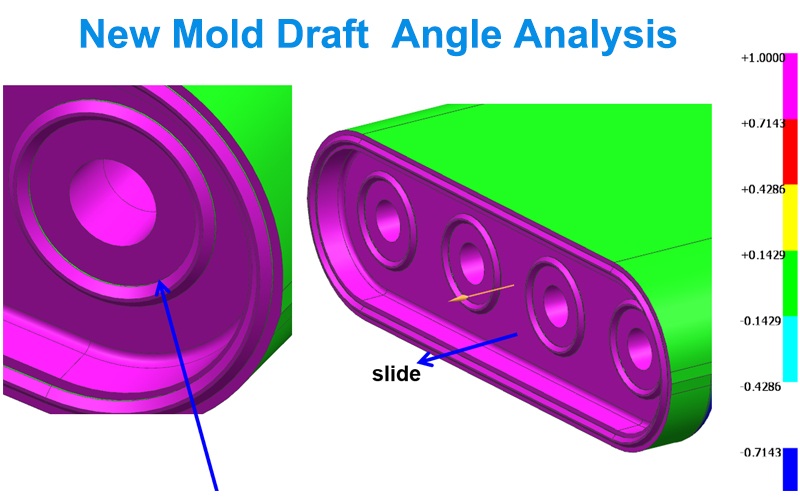
What Exactly is a Draft Angle?
In simplest terms, a draft angle is the angle measured between the vertical wall of a part and the direction of mold opening (or the line of draw). It creates a slight taper, making the opening of a cavity slightly wider than its base.
Visual Analogy: Think of an ice cube tray. The compartments are slightly wider at the top than the bottom. That taper is the draft angle. Without it, the ice would lock itself in place.
Proper implementation reduces ejection forces, prevents part damage, minimizes cosmetic defects, and extends mold life, directly impacting manufacturing efficiency and part quality.
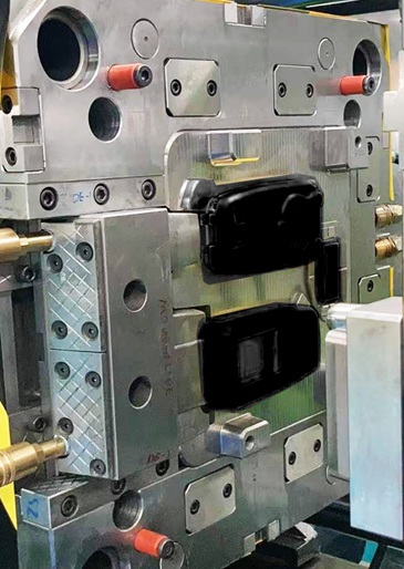
Why is Draft Essential? The Physics of Demolding
During molding, material (plastic, metal, etc.) is forced into a mold cavity under high pressure and often heat. As it cools and solidifies, it shrinks, gripping the mold walls with significant force. A vertical wall creates a mechanical lock.
A draft angle breaks this lock by:
Reducing Surface Contact: The part contacts the mold wall only along a tapered line, not a full parallel surface.
Creating a Wedge Effect: During ejection, the part is effectively “wedged” out of the cavity. The angled surface converts some of the vertical ejection force into a lateral component, easing release.
Preventing Drag Marks: Without draft, the part scrapes along the mold wall during ejection, causing unsightly and functional scratches.
How to Design with Draft Angle in the Mold Manufacturing: Practical Guidelines
Designing a draft angle isn’t just about slapping on an angle. It requires forethought and strategy.
1. Apply Draft Angle Early
Incorporate draft angles in the initial mold design phase, not as an afterthought. Adding it later often compromises aesthetics and function.
2. Direction is Key
The draft angle must always favor the direction of the mold opening. Identify the parting line (where the two halves of the mold meet) and ensure all features taper away from it. For complex plastic parts with side actions or cores, the draft angle direction must align with the specific movement of each component.
3. Where to Add Draft Angle (and Where to Avoid It)
ADD DRAFT ANGLE TO: All vertical walls, ribs, bosses, and internal cavities.
MINIMIZE/CAREFULLY CONSIDER DRAFT ON: Functional sealing surfaces, areas for adhesive bonding, or interfaces with other components. Here, you may need to negotiate the smallest acceptable angle.
4. The “More is Better” Principle
Within reason, a larger draft angle always makes demolding easier, improves part quality, and can reduce cycle time. The goal is to use the largest draft angle your design can tolerate.
1.0 Theoretical Foundation: Mechanical Interference and Release Mechanics
1.1 The Demolding Force Equation
The necessity for draft derives from the fundamental ejection force equation:
Fₑ = Fₐ × (μ × cos α – sin α)
Where:
Fₑ = Ejection force required
Fₐ = Adhesion force (polymer-steel interface)
μ = Coefficient of friction (polymer on mold steel)
α = Draft angle
Without draft (α=0°), the equation simplifies to Fₑ = Fₐ × μ, representing maximum resistance. As α increases, the trigonometric relationship creates a mechanical advantage, with the sin α component acting against friction. The critical threshold occurs when μ × cos α = sin α, theoretically enabling zero-force ejection.
1.2 Polymer-Steel Interface Physics
Adhesion force (Fₐ) comprises multiple components:
Mechanical interlocking with surface roughness (Ra)
Van der Waals forces amplified at microscopic level
Electrostatic adhesion particularly pronounced in crystalline polymers
Thermal shrinkage pressure as polymer cools below heat deflection temperature
Amorphous polymers (e.g., ABS, PC, PMMA) typically require less draft than semi-crystalline materials (e.g., PP, PA, POM) due to differential shrinkage behavior and lower built-in stress at the interface.
2.0 Systematic Design Methodology
2.1 Draft Angle Specification Protocol
Refer to the flowchart on the right.
2.2 Depth-Dependent Draft Calculations
For walls exceeding 50mm in depth, apply the proportional draft formula:
αᵣ = αₒ + (D/100) × k
Where:
αᵣ = Required draft angle (degrees)
αₒ = Base draft from texture requirements
D = Wall depth (mm)
k = Material factor (0.01-0.03 for typical engineering plastics)
2.3 Critical Geometries Requiring Special Consideration
Boss Design:
External walls: α ≥ 0.5°
Internal draft for core pins: α ≥ 1° + 0.02° per mm of depth
Height-to-diameter ratio > 3: Add 0.25° per additional ratio unit
Rib Design:
Rib height ≤ 3 × nominal wall thickness
Draft per side: ≥ 1° for smooth finishes
Add 0.5° minimum for textured applications
Radius at base: 0.25-0.5 × nominal wall thickness

3.0 Texture-Specific Draft Angle Specifications
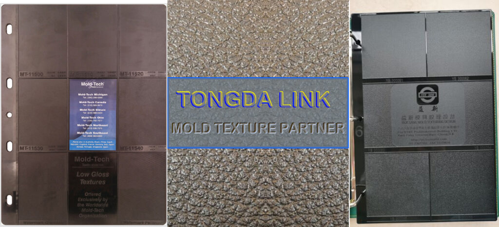
Texture Application Rule: For every 0.01mm of additional texture depth beyond SPI-A1, add 0.25° minimum draft angle.
|
SPI Finish Standard |
Rₐ (μm) |
Visual Reference |
Minimum Draft (Cavity) |
Minimum Draft (Core) |
Technical Rationale |
|
A-1 (Mirror) |
0.012-0.025 |
Optical clarity |
0.5° |
1.0° |
Micro-welding risk at high polish interfaces |
|
A-2 (High Gloss) |
0.025-0.05 |
Appliance finish |
0.75° |
1.25° |
Reduced mechanical interlocking |
|
B-1 (600 Grit) |
0.05-0.10 |
Fine matte |
1.0° |
1.5° |
Directional grain requires additional clearance |
|
C-1 (600 Grit ST) |
0.10-0.15 |
Satin texture |
1.5° |
2.0° |
Multi-directional grain pattern |
|
C-2 (400 Grit) |
0.20-0.30 |
Fine leather |
2.0° |
2.5° |
Texture depth approaches 0.01mm |
|
C-3 (320 Grit) |
0.30-0.40 |
Medium leather |
2.5° |
3.0° |
Visible grain requires significant clearance |
|
D-1 (Dull) |
0.40-0.55 |
Concealment grain |
3.0° |
3.5°+ |
Aggressive light scattering surface |
|
D-2 (Textured) |
0.55-0.70 |
Deep pattern |
3.5° |
4.0°+ |
Mechanical interlocking becomes significant |
|
D-3 (Heavy) |
0.70+ |
Custom textures |
4.0°+ |
4.5°+ |
Each texture valley creates micro-undercuts |
4.0 Material-Specific Considerations
4.1 Shrinkage Compensation Effects
Semi-crystalline materials exhibit higher shrinkage (1.5-3.0%) compared to amorphous materials (0.5-0.7%). This shrinkage typically occurs toward the center of mass, creating additional gripping force on cores:
Draft Compensation Factor (DCF) = S × h × tan α
Where:
S = Material shrinkage rate (%)
h = Wall height (mm)
α = Nominal draft angle
For materials with >2% shrinkage, increase calculated draft angles by 15-25%.
4.2 Friction Coefficient Variations
|
Polymer Family |
μ (on P20 Steel) |
Draft Multiplier |
|
ABS |
0.35-0.45 |
1.0× (baseline) |
|
Polycarbonate |
0.40-0.50 |
1.1× |
|
Polypropylene |
0.25-0.35 |
0.9× |
|
Nylon 6/6 |
0.30-0.40 |
1.0× |
|
Acetal (POM) |
0.20-0.35 |
0.85× |
|
TPU |
0.50-0.70 |
1.3× |
5.0 Advanced Implementation Techniques
5.1 Progressive Draft Angles
For deep draw parts (>100mm), implement variable draft:
0-25mm depth: α₁ (base angle)
25-75mm depth: α₂ = α₁ + 0.5°
75mm depth: α₃ = α₂ + 0.5°
This progression accommodates increasing ejection force over the stroke length while minimizing cosmetic impact at the opening.
5.2 Parting Line Optimization
The parting line represents the optimal zero-draft location. Design strategy:
- Position parting lines at maximum cross-section
- Draft away from the parting line in both mold halves
- For stepped parting lines, maintain consistent draft direction relative to each segment
5.3 Undercut Management vs. Draft
When the draft cannot be applied due to functional requirements:
- Consider side actions or lifters for <1° draft situations
- Collapsible cores for internal undercuts
- Allow for sacrificial draft in non-critical areas, followed by post-mold machining
6.0 Validation and Simulation
6.1 Mold Flow Analysis Integration
Modern simulation software (Moldflow, Moldex3D) can predict:
Ejection force calculations with varying draft angles
Shrinkage warpage as function of draft geometry
Cooling line effects on differential shrinkage
6.2 Empirical Validation Protocol
First Article Inspection: Measure actual draft versus specification
Ejection Force Monitoring: Instrument mold with load cells
Surface Analysis: White light interferometry for texture depth verification
Dimensional Stability: CMM measurement after 24-hour stabilization
7.0 Economic Implications
Proper draft angle specification directly impacts:
Cycle time reduction: Up to 15% decrease with optimal draft
Mold maintenance: Reduced polishing and repair frequency
Scrap rate minimization: Lower ejection-related defects
Tool life extension: Reduced wear on ejector systems
TONGDA LINK IS YOUR MOLD PARTNER
Draft angle design demands collaboration between product designers, mold engineers, and processing technicians from conceptual design through production validation. The design for proper draft specification exponential returns in manufacturing efficiency and part quality throughout the product lifecycle.