

The gate is the final point of entry for molten plastic into the mold cavity, making its design one of the most critical decisions in the injection molding process. A well-designed gate produces flawless parts with minimal waste, while a poor choice can lead to defects, production delays, and increased costs.
At TONGDA LINK, our mold engineers provide mold makers and product engineers with a comprehensive overview of gate design. This guide covers the fundamental definition of a gate, explores common gate types, and offers practical strategies for selecting and designing the optimal gate for your plastic parts.
WHAT IS A MOLD GATE?
A mold gate, also referred to as a feed gate, is the narrow channel that connects the runner to the mold cavity. It is typically the shortest and smallest cross-sectional segment of the entire gating system. In metal casting, it describes the entry point and passage through which molten metal flows into the mold during pouring, and is often used interchangeably with the broader gating system.
In plastic injection molding, the gate plays several critical roles:
-
It accelerates material flow by creating a constricted flow surface.
-
The resulting high shear rate improves material fluidity.
-
Viscous heating raises the melt temperature locally, reducing viscosity for easier filling.
During the molding cycle, the gate is the first section to solidify and seal. This early solidification prevents material backflow and maintains cavity pressure, reducing the risk of shrinkage and surface defects like sink marks in the final part. After ejection, the gate is easily removed, separating the runner system from the molded component.
ESSENTIAL FUNCTIONS OF INJECTION MOLDING GATES:
In simpler terms, the gate is the precisely engineered opening in the injection mold that links the runner system to the part cavity. It performs several essential functions:
-
Controls Flow: Regulates the speed and pressure of molten plastic entering the cavity, ensuring rapid and complete filling.
-
Directs Packing: Allows additional material to be forced into the cavity to compensate for volumetric shrinkage during cooling.
-
Seals the Cavity: Solidifies first (freezes off) to retain pressure and seal the cavity to prevent backflow. This prevents defects such as shrinkage cavities or surface depressions.
-
Determines Parting Point: Affects where the finished part detaches from the runner system after molding, influencing both appearance and post-processing requirements.
HOW TO CHOOSE A MOLDING GATE?
The selection of an appropriate gate type depends on several factors, including the product’s appearance requirements, its size and geometric constraints, and the type of plastic being used. Both the shape and dimensions of the gate significantly influence the quality of the final molded part. In most cases—excluding main-runner gates—the gate represents the smallest cross-sectional area within the runner system. Its cross-sectional area is typically about 3–9% that of the branch runners, with a common rectangular or circular profile and a step length of approximately 1–1.5 mm.
Precision Mold Manufacturing Solutions from TONDDA LINK
At TONDDA LINK, with years of experience in plastic mold manufacturing, we generally prefer to use small gates in our mold designs due to the following key advantages:
-
Enhanced Flow Rate: Small gates increase the flow velocity of the molten plastic. The greater pressure differential across a small gate reduces the apparent viscosity of the material, thereby facilitating easier mold filling.
-
Increased Material Temperature: The high frictional resistance within a small gate converts a portion of the flow energy into frictional heat as the plastic passes through. This localized temperature rise improves fluidity, which is especially beneficial for producing thin-walled parts or components with fine surface details.
-
Improved Control of Filling and Reduced Internal Stress: Small gates help regulate and shorten the filling time. Because they solidify quickly after injection, the holding pressure stage is precisely terminated, reducing the orientation and strain of solidified macromolecules. This results in lower internal stress within the part and contributes to a shorter overall molding cycle.
-
Balanced Multi-Cavity Filling: Small gates introduce higher flow resistance, ensuring that the runner system fills completely and builds sufficient pressure before material enters each cavity. This promotes simultaneous cavity filling and minimizes imbalances in feed rates across multiple cavities.
-
Easier Post-Processing: Small gates are easier to remove manually, and the residual gate marks are minimal, reducing the need for extensive grinding or finishing work.
However, it is important to note that excessively small gates can significantly increase flow resistance and prolong mold filling time. They are generally not suitable for high-viscosity materials or plastics whose apparent viscosity is not significantly affected by shear rate.
GATE TYPES AND APPLICATIONS
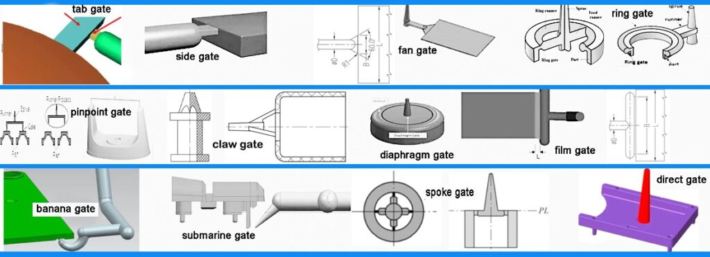
Mold gate types mainly include common forms such as direct gate/sprue gate, side gate/edge gate, overlapping gate/lapped edge gate, tab gate, pinpoint gate/pin gate, submarine gate/sub gate, banana gate, and secondary gate. Other types, such as fan gate, thin-plate gate (flat-slit gate), ring gate, disc gate, diaphragm gate, spoke gate/spider gate, and claw gate, are also used in specific applications.
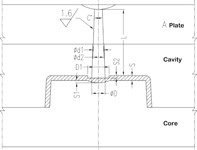
1, DIRECT GATE / SPRUE GATE:
TONGDA LINK HELPS YOU TO CHOOSE THE MOLD GATE
2, EDGE GATE / SIDE GATE:
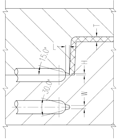
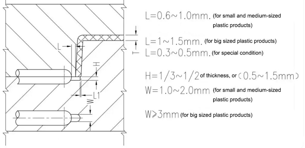
A side gate, also known as a rectangular gate, is typically located on the parting line, allowing material to enter from the outside of the cavity. Because side gates are generally small, the relationship between their cross-sectional shape and pressure/heat loss is negligible. Side gates are simple in shape, easy to process, and their dimensions are easily controlled. They are also easy to modify, making them suitable for various shapes of products. However, they are not suitable for PC materials or transparent parts. Their disadvantages include noticeable gate defects on the product surface, requiring manual trimming of the runner. They are also prone to flow marks during molding, making them unsuitable for thin, transparent products, as well as long, thin, cylindrical products.
L=0.6~1.0mm. (For small, medium-sized plastic products)
L=1~1.5mm. (For big-sized plastic products)
L=0.3~0.5mm. (For special condition)
H=1/3~1/2 of wall thickness, or (0.5~1.5mm)
W=1.0~2.0mm. (For small, medium-sized plastic products)
W>3mm. (For big-sized plastic products)
3, OVERLAPPING GATE / LAPPED EDGE GATE:
This configuration makes them a typical impact-type gate, which offers several functional benefits:
- Prevents eccentricity and welding in cylindrical components.
- Reduces jetting of molten plastic.
- Avoids serpentine flow patterns.
Advantages:
- Easy to manufacture.
- Helps in achieving a better surface finish.
Disadvantages and Limitations:
- The gate does not self-separate from the part, requiring manual removal.
- Gate removal is difficult, often requiring diagonal pliers or specialized tools.
- Leaves prominent gate marks on the part surface.
- Finishing the gate area is challenging.
- High pressure loss during injection.
- Improper molding conditions may lead to surface pits at the gate location;
- Not suitable for PVC and PU plastics.
4, TAB GATE/WINGED GATE:
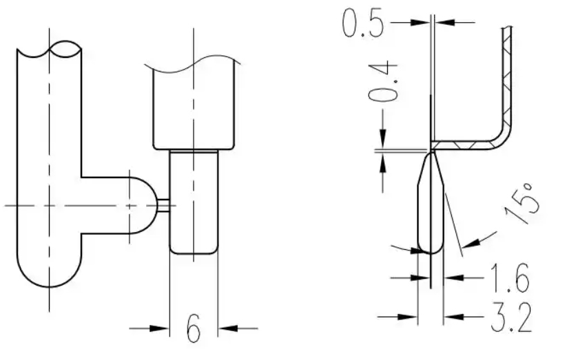
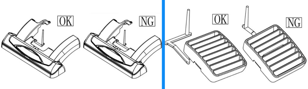
A tab gate—also referred to as a winged gate or trim gate—features a wing-shaped or fan-shaped extension attached to the part at the gate location. Molten plastic flows through the main gate and into this wing before entering the cavity. The frictional heat generated in this extended section improves the plastic’s fluidity, reduces flow velocity, and changes its direction. This design minimizes stress concentration, promotes smoother filling, and reduces the occurrence of weld lines and flow marks often associated with standard side gates.
Applications
This gate type is particularly well-suited for:
- Thin-walled or large-area products requiring uniform filling.
- Applications where gate marks are not permitted on the part surface, such as high-transparency flat products and components, where minimal deformation is critical.
Design Context
In mold design, the wing gate is often implemented as a variant or partial extension of a fan gate. In most cases, it specifically refers to the wing-shaped extension of a fan gate or a widened version of a tab gate.
TONGDA LINK MAKES MOLDS TO SUPPORT AUTOMATIC MOLDING PRODUCTION.
5, PINPOINT GATE / PIN GATE:
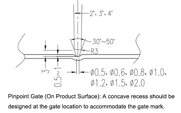
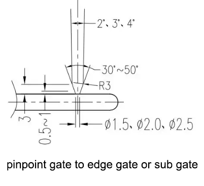
A point gate, also known as a pin gate, leaves very little injection mark and can be used for almost all types of products. It offers greater flexibility in location selection, has lower residual stress near the gate, and can self-break off, enabling automated production. For larger products, multiple injection points can be used simultaneously, shortening the process and reducing deformation caused by flow resistance.
Point gates are particularly suitable for cylindrical, shell-shaped, and box-shaped products. Cylindrical gears typically use point gates, with three points designed on their end face to ensure injection balance.
However, because point gates result in greater injection pressure loss and require higher injection molding pressure than direct gates, they often require a three-plate mold (also known as a double parting line) structure, leading to a more complex mold structure and a longer molding cycle.
6, SUBMARINE GATE / SUB GATE:
A submarine gate, also known as a sub gate, offers greater flexibility in its design.
Sub gate can be machined to precise dimensions without any shape mismatch issues. It can be installed on either the inner or outer surface of the product. During demolding, the gate is automatically removed from the product with minimal traces, making it suitable for automated production. Submersible gates are suitable for almost all plastics, but are not recommended for PC, PMMA, and SAN products. In practice, submersible gates are increasingly used.
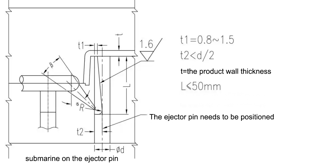
Based on their location, submarine gates can be categorized into three types: submarine upper mold (on the product), submarine lower mold (on the product), and submarine ejector pin.
6-1, SUBMARINE UPPER MOLD:
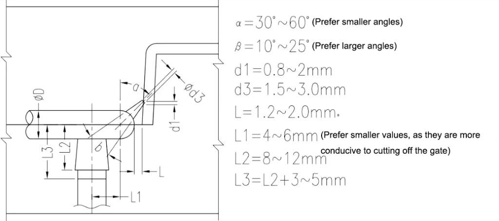
Submarine upper mold (submarine on the outer wall of the product). This type of gate requires customer approval and should not be used arbitrarily. It is also important to ensure that the gate and the upper mold wall are not completely open.
6-2, SUBMARINE LOWER MOLD:
Submarine lower mold (submarine on the outer wall or rib of the product);
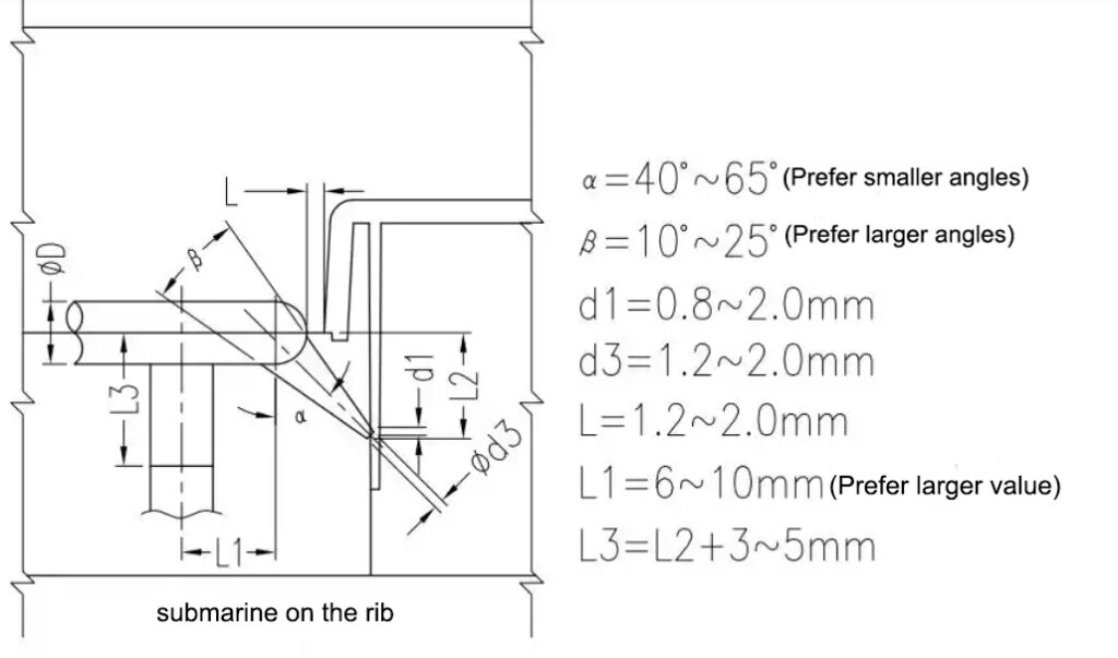
6-3, SUBMARINE EJECTOR PIN:
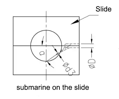
6-4, SUBMARINE SLIDE:
When the product uses a half slide, the gate can be submerged on either side of the slide.
7, BANANA GATE:
Banana-shaped gates, also known as arc-shaped submerged gates, have the following main characteristics:
- ① Automatic gate trimming.
- ② Concealed gate entry point.
- ③ Gates can be inserted at the same height on the runner surface.
Common defects of banana-shaped gates:
- ① Incomplete gate ejection or unsightly breakage.
- ② Roughness on the gate entry surface.
- ③ Gate ejection rebound causing damage to the product.
- ④ Incomplete or unbalanced gate ejection.
ASK PRICE FOR PLASTIC MOLDS MAKING
Structure And Parameters of Banana-Shaped Gates:
A. Structure and parameters of banana-shaped gates for small plastic parts:
The structure of a banana-shaped gate for small plastic parts (runner diameter d < 8mm) is shown in the following figure.
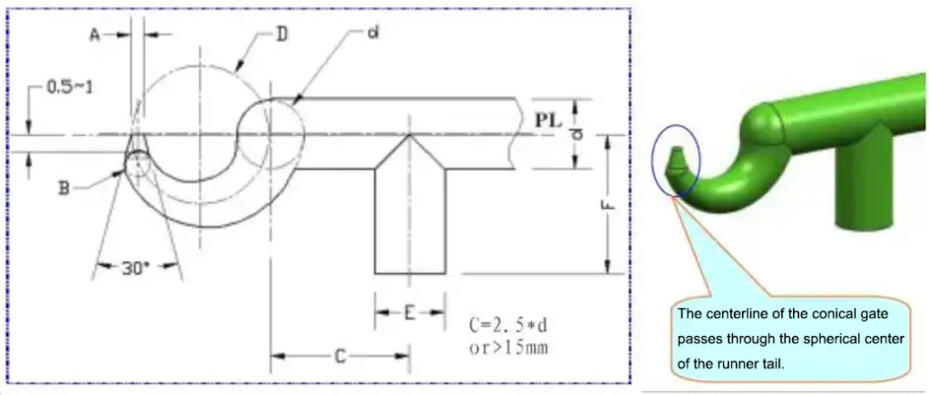
Structural Parameters of Banana Gates For Small Plastic Parts:
|
Classification |
A |
B |
D |
d |
E |
F |
|
|
Small Plastic Parts (d<Φ8.0) |
Non Gas-Assisted |
Φ0.7~Φ1.0 |
Φ1.5~Φ3.0 |
2~3XΦd |
Φ4~<Φ8 |
Φ4~Φ8 |
>D |
|
Small Plastic Parts (d<Φ8.0) |
Gas-Assisted Injection |
Φ0.7~Φ1.5 |
Φ1.5~Φ3.0 |
2~3XΦd |
Φ4~<Φ8 |
Φ4~Φ8 |
>D |
B. Structural and parameters of banana gates for large and medium-sized plastic parts:
The structure of a banana-shaped gate for large and medium-sized plastic parts (runner diameter d > 8mm) is shown in the following figure.
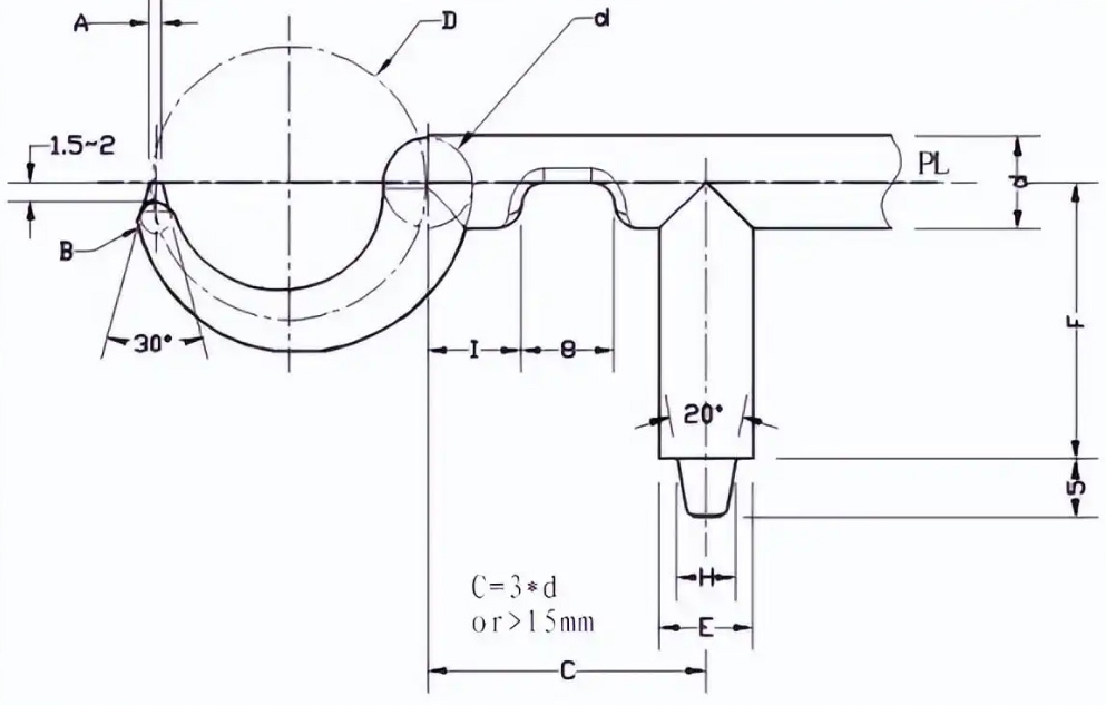
Structural Parameters of Banana Gates For Large and Medium-Sized Plastic Parts:
|
Classification |
A |
B |
D |
d |
E |
F |
H |
I |
|
|
Large and Medium-Sized Plastic Parts (d>Φ8.0) |
Non Gas-Assisted |
Φ1.0~Φ1.6 |
Φ3.0~Φ4.0 |
3~5XΦd |
Φ8~<Φ12 |
Φ8~<Φ12 |
>D |
E-3.0 |
d |
|
|
Gas-Assisted Injection |
Φ1.5~Φ4.0 |
Φ3.0~Φ5.0 |
3~5XΦd |
Φ8~<Φ12 |
Φ8~<Φ12 |
>D |
E-3.0 |
d |
Structural Design Considerations for Banana Gates:
① If there are multiple gates, they should be distributed evenly; if there is only one gate, an auxiliary runner can be added to balance the distribution. See the diagram below.
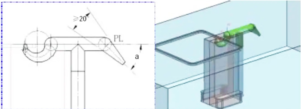
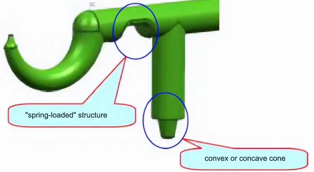
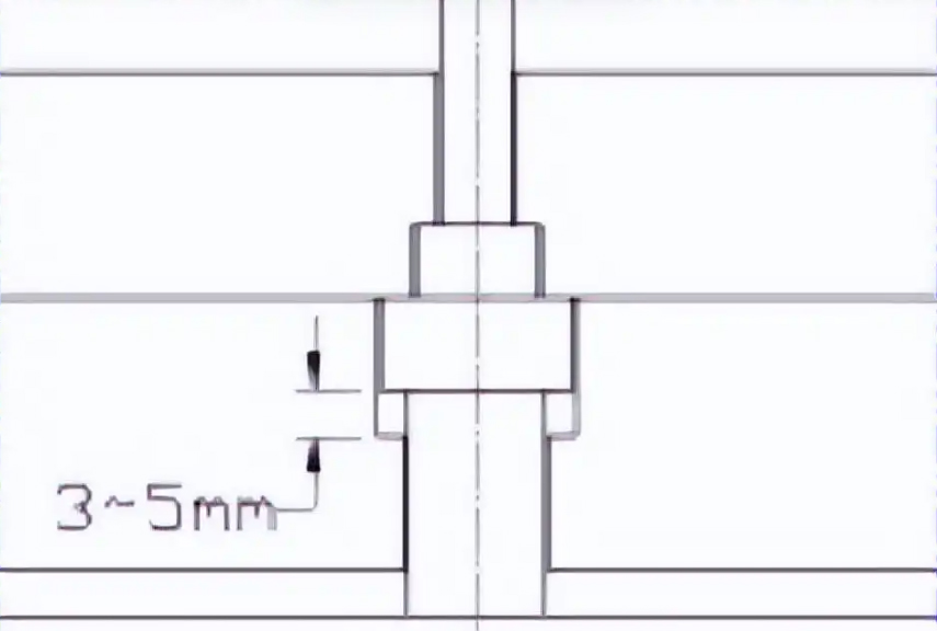
④ To further improve the gate cut and reduce the possibility of product impact when the banana sprue is ejected, a 3-5mm delay structure can be installed under the sprue hook of the banana gate, as shown in the figure below.
Structural Types of Banana Gate Inserts:
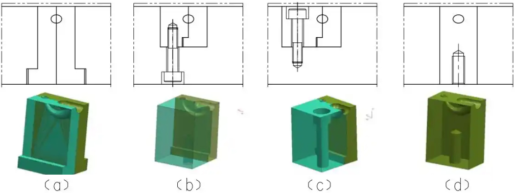
The banana gate has a complex shape. A single-piece structure would be difficult to manufacture, while an insert-based assembly simplifies the manufacturing process and facilitates maintenance. The insert-based structural types are shown in the diagram below, where (a) is a mounting bracket connection, suitable for small molds; (b) is a bottom screw connection; (c) is a top screw connection, suitable for medium and large molds; and (d) is a single-piece structure, such as the standard banana-shaped struct inserts from LKM and HASCO.
LAUNCH MOLDS MANUFACTURING FOR YOUR PLASTIC PRODUCTS NOW
8, SECONDARY GATE:
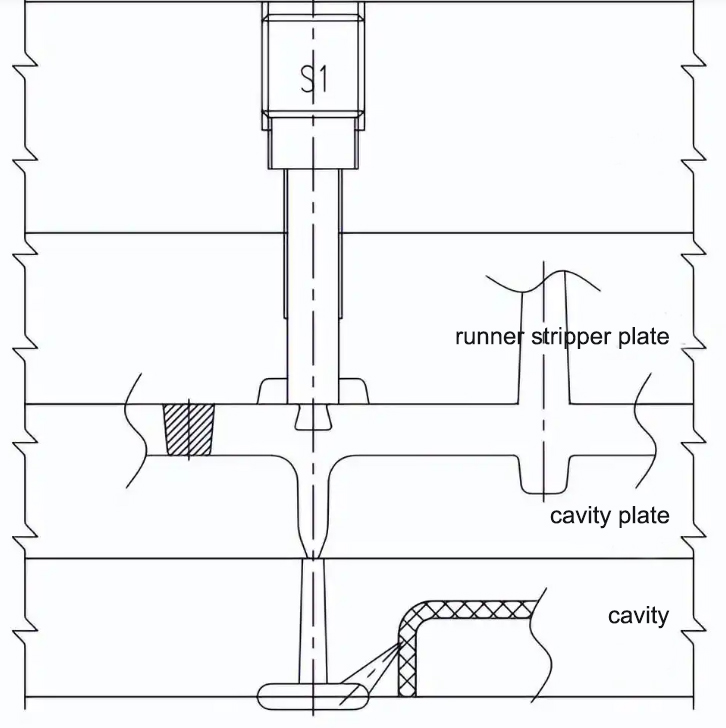
A secondary gate is a smaller gate designed between the runner and the main gate. This allows the plastic to experience a high shear rate as it flows through the first gate, reducing its apparent viscosity. At the same time, the frictional heat increases the temperature of the molten plastic, thereby improving its fluidity.
The Main Function of The Secondary Gate:
Other Gates for Specific Applications
Fan gate, thin-plate gate (flat-slit gate), ring gate, disc gate/diaphragm gate, spoke gate/spider gate, and claw gate
9, FAN GATE:

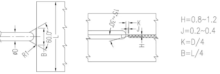
A fan-shaped gate is a gradually expanding gate, a variation of the side gate, often used for molding wide sheet-like plastic parts, flat products, and shallow shell or box-shaped products. The gate gradually expands in a fan shape from the runner towards the cavity, gradually widening and thinning along the feed direction. This results in a uniform distribution of the molten plastic across its width, reducing internal stress and warpage during injection; it also provides good venting of the cavity, preventing trapped air. However, gate removal is difficult, leaving noticeable marks.
10, FILM GATE (THIN-PLATE GATE, FLAT-SLIT GATE):
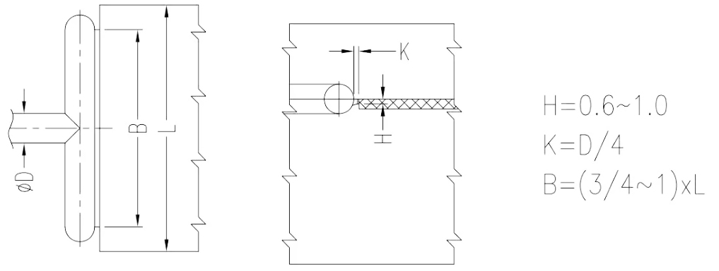
A film gate (also referred to as a thin-plate gate or flat-slit gate) is a variation of the side gate, primarily used for molding large, flat plastic parts (as shown in Figure 8). In this design, the distribution channel runs parallel to the edge of the mold cavity and is known as a parallel runner. Its length can be equal to or greater than the width of the part. During injection, the molten plastic is first evenly spread within the parallel runner before flowing uniformly into the cavity at a low linear velocity. This results in reduced internal stress within the part, minimizing warping and flow marks caused by directional stress. Additionally, it promotes effective venting, making the final product less prone to air bubbles. However, disadvantages include the need for significant gate removal effort and noticeable gate marks on the finished part.
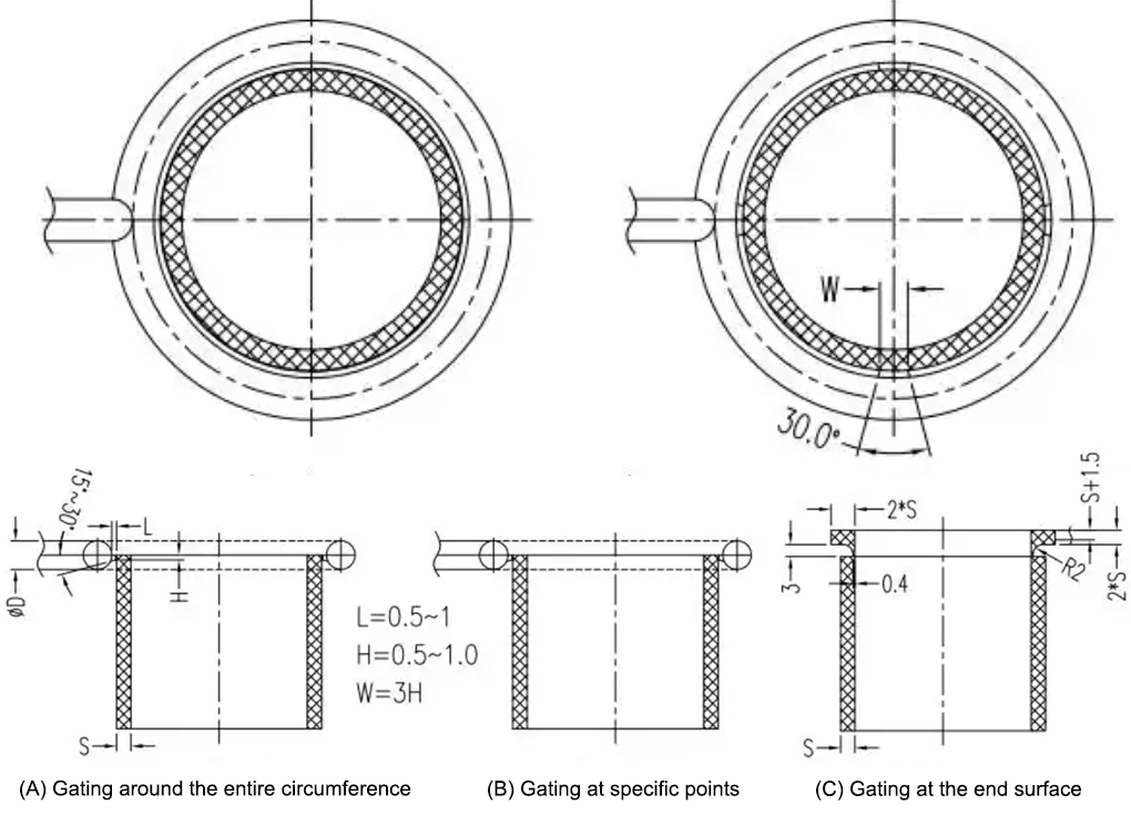
11, RING GATE:
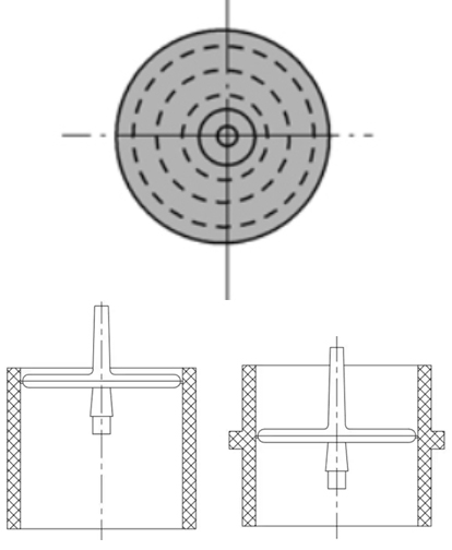
12, DISC GATE(DIAPHRAGM GATE):
LEARN MORE ABOUT TONGDA LINK MOLD MANUFACTURING
13, SPOKE GATE/SPIDER GATE:
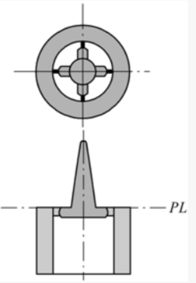
The application scope of the spoke gate is similar to that of the disc gate. It is also suitable for plastic parts with rectangular inner holes. It changes the entire perimeter feeding to several small arc or straight feeding segments. Therefore, it can be regarded as an inner gate. This type of gate is easy to cut off, has less solidified material in the runner, and the upper part of the core is positioned, which increases the stability of the core. However, weld lines on the plastic part affect the strength and appearance quality of the plastic part.
14, CLAW GATE:
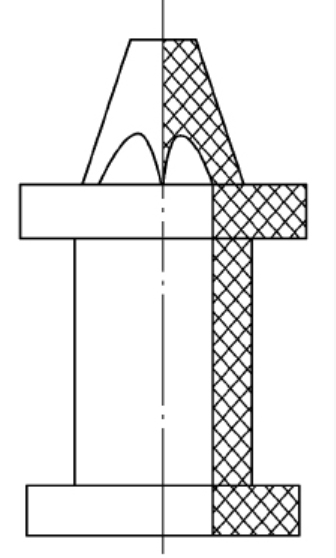
A variation of the spoke gate, it features runners on the tapered cross-section of the core. It feeds material at several points along the circumference, with the runners and claws not on the same plane. The top of the core extends into the mold cavity, acting as a positioning element to ensure the coaxiality of the inner hole and outer circle of the plastic part. However, this results in several seams on the plastic part, affecting its strength. This type of gate is suitable for tubular plastic parts, especially those with small inner holes or high coaxiality requirements. Key features: In a single-cavity mold, the gate is connected to the main runner; in a multi-cavity mold, the gate is connected to the vertical runners.
DESIGN PRINCIPLES FOR MOLD GATES
(1) Gate Location Based on Wall Thickness
(2) Ease of Removal and Aesthetics
(3) Flow Uniformity and Venting
(4) Avoiding Weld Lines and Flow Marks
(5) Multi-Cavity Molds
(6) Protecting Cores and Inserts
(7) Managing Shrinkage
(8) Runner and Gate Geometry
How to Select and Design Your Gate: A 5-Step Framework
Conclusion: Gate Design as an Exercise in Optimization
Gate design is fundamentally an exercise in informed compromise. It requires balancing competing priorities: aesthetics versus function, cost versus cycle time, and production efficiency versus part quality. While a single “perfect” solution rarely exists, the objective is to define the most optimal configuration for the specific part, material, and production context.
By systematically applying these principles, mold designers move beyond trial and error, transforming gate design from a potential variable into a controlled parameter that actively safeguards part quality and process stability. The gate may be small in size, but it is a critical feature that governs the success of the entire injection molding operation.