INTRODUCTION
Warpage is one of the most common dimensional defects in injection molding. Many injection molding technicians treat it as a purely processing issue, endlessly tweaking parameters—only to achieve limited improvements or even worsen the problem.
TONGDA LINK MOLD MANUFACTURING, as a seasoned mold supplier, we are proud to share our proven expertise in resolving plastic product deformation. This article systematically breaks down the seven root causes of warpage and their corresponding solutions across four dimensions: part design, mold cooling, material properties, and molding process. It also provides a practical, step-by-step troubleshooting sequence to help you eliminate deformation in the finished part.
Shrinkage Controlled. Quality Assured.
The Core Essence of Warpage in Injection-Molded Parts
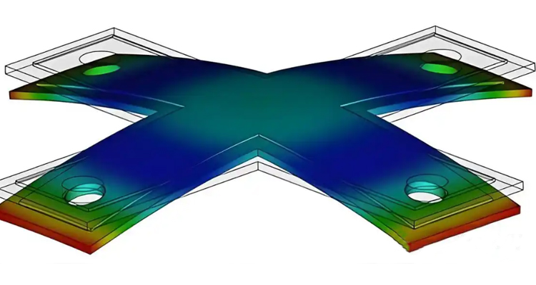
The warpage of plastic part is the result of uneven shrinkage across different areas of a part, which prevents internal residual stresses from balancing. After cooling, the part bends toward the side that shrinks more. Any factor that creates “uneven shrinkage” is a potential source of warpage.
Critical Insight: For the same temperature difference, thermal expansion and contraction in large plastic molded parts are several times greater than in small ones. This is why warpage is particularly severe in large, thin-walled plastic parts.
Seven Root Causes of Warpage and Their Solutions
1, Uneven Wall Thickness – The Most Frequent Source of Warpage
Cause: In transitions between thick and thin walls, thicker sections are difficult to pack, cool more slowly, and continue shrinking after ejection. Thinner sections cool faster and shrink less. This differential creates internal stress, bending the part toward the thicker wall.
High-Risk Locations: Rib roots, boss backs, and abrupt wall thickness junctions.
Solutions (Design Phase):
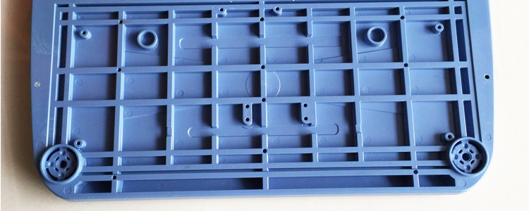
Ribs, boss pillars, and wall-thickness transitions must be designed at reasonable locations and ensure adequate contact areas.
Rib height ≤ 3× nominal wall thickness.
Rib base width ≤ 60% of nominal wall thickness.
Use gradual transitions (buffer ribs or chamfers) instead of step-like changes.
During mold design, engineers should consider placing gates in thick-wall areas to ensure effective pressure transmission.
Solutions (Post-Mold Fabrication):
Adjust cooling channels to enhance heat removal in thick zones.
Extend cooling time specifically for thick-wall sections.
Think Your Part Geometry Is Too Complex For Zero Deformation? We’re Ready To Prove You Wrong. Request a Feasibility Analysis.
2, Uneven Mold Cooling – The Consequence of Large Temperature Differences
Cause: Areas that cool quickly have lower shrinkage; areas that cool slowly allow polymer chains to align more, increasing shrinkage. Studies show that for every 10% increase in cooling time, warpage caused by uneven shrinkage drops by over 30%.
Therefore, adequate cooling time can effectively improve warpage; however, excessive cooling can increase residual stress and the risk of post-molding shrinkage. While finding the optimal cooling time is crucial, the layout of cooling channels and the temperature of the cooling medium are equally important. When the temperature difference between the fixed half (cavity) and the moving half (core) is too large, the shrinkage rates on both sides differ. The material near the hotter side shrinks more, causing the part to bend toward that side. Thus, cooling time during injection molding requires multiple mold trials for verification.
Troubleshooting: Use an infrared thermometer to check mold surface temperatures. The difference between fixed and moving halves must be ≤ 10°C. Inlet/outlet water temperature differences should be ≤ 5°C.
Solutions:
Add cooling channels to insufficiently cooled areas.
Inspect channels for blockages or scale.
Use beryllium copper inserts in areas with poor thermal conductivity.
Switch to a mold temperature controller instead of direct water cooling.
3, Improper Gate Location and Quantity
Cause: Gate location dictates melt flow direction. For semi-crystalline materials (PP, PA, POM), shrinkage in the flow direction is significantly higher than in the transverse direction—differences can reach 30%.
This anisotropy directly causes warpage after molding. Long, rectangular parts or large flat plates with single-point or eccentric gates carry the highest warpage risk. In actual production, a “serpentine runner design” is a common method to ensure uniform distribution of polymer molecular chains and normalize shrinkage.
Solutions:
Move the gate to the geometric center or axis of symmetry.
Increase the number of gates to shorten flow length and reduce anisotropy.
If mold modification is impossible, use multi-stage holding pressure for compensation.
4, Improper Holding Pressure Parameters
Insufficient Holding Pressure: If the total injection and holding time is shorter than the gate seal time, the melt loses pressure prematurely, leading to inadequate compensation for cooling shrinkage. Residual internal stress is released instantly, causing voids and excessive outer shrinkage.
Excessive Holding Pressure: The outer layer solidifies while the inner core is still pressurized, creating residual stress that causes “delayed warpage” (deformation hours after ejection).
Diagnostic: Measure part dimensions immediately after ejection and again 24 hours later. Significant changes indicate residual stress release.
Solutions:
Set holding pressure to 50–80% of injection pressure.
Adopt multi-stage holding: high pressure for rapid compensation, lower pressure for maintenance.
Precisely control the switchover timing from injection to holding.
Extend holding time to allow continuous melt replenishment.
5, Improper Melt or Mold Temperature Settings
Melt Temperature: If the melt temperature is too high, molecular chain movement intensifies, accelerating material degradation and increasing the shrinkage rate. Conversely, lower-temperature melt shrinks less. When these two types of melt with different characteristics coexist in the same cavity due to uneven temperature, warpage will tend toward the “hotter” side. Additionally, excessive fluidity can lead to over-packing and increased residual stress.
Mold Temperature: Lower mold temperatures freeze molecular chains faster, synchronizing shrinkage. However, for semi-crystalline materials, incomplete crystallization can lead to unstable post-mold shrinkage.
If the part’s operating temperature exceeds room temperature, severe thermal expansion and contraction may cause secondary deformation. High mold temperatures extend the cooling cycle and worsen dimensional stability, but they reduce internal stress. The optimal mold temperature range must balance long-term product stability with the difficulty of post-processing.
Solutions:
Set parameters according to the ranges recommended in the material’s technical data sheet.
Measure actual mold temperatures (set values often differ from reality).
For hygroscopic materials (PA, PC, PBT), ensure drying time and temperature meet specifications.
6, Uneven Ejection Forces
Cause: Unreasonable ejector pin layouts create localized stress. If a part is forced out before fully cooled, it finishes cooling in a non-free state, causing warpage—especially in thin-walled, large flat parts.
As mentioned earlier, larger parts experience significantly greater thermal expansion and contraction for the same temperature difference, making large thin-walled parts the first to warp.
Troubleshooting: Observe whether the warped location corresponds to the ejector pin positions. Check for localized stress whitening or mold sticking during ejection.
Solutions:
Optimize ejector pin layout for uniform force distribution.
For large flat parts, use a stripper plate instead of point ejectors.
Extend cooling time to ensure complete solidification before ejection.
Verify adequate draft angles to reduce lateral pulling forces.
7, Anisotropic Material Shrinkage (Inherent Property)
Cause: Semi-crystalline materials (POM, PP, PA, PBT, PE) inherently shrink differently in flow vs. transverse directions due to molecular alignment. Processing can only mitigate, not eliminate, this.
Risk Ranking (Highest to Lowest Anisotropy): POM > PP > PA > PBT > PE. Amorphous materials (ABS, PC, PS) are far easier to control.
Solutions:
Prioritize amorphous materials for warpage-sensitive applications.
Add glass fiber to semi-crystalline materials to significantly reduce anisotropy.
Add ribs in the design phase to mechanically resist deformation.
Use Moldflow simulation to predict warpage direction and guide gate/cooling design.
Need a Mold That Delivers Consistent 0.1mm Tolerance? Get a No-Obligation Quote in 24 Hours.
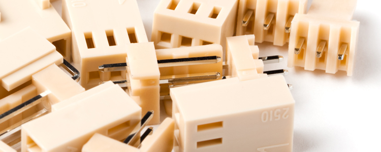
Advanced Mold Structure – Preventing Temperature Variations Before the Gate
Hot Runner + Precise Temperature Control: Ensure uniform melt temperature across all runner sections, eliminating hot/cold spots.
Multi-Stage Holding Switchover: Pack thick-wall areas earlier and thin-wall areas later to flatten the shrinkage curve.
Lateral Ejection with Auxiliary Pins: Use mechanical force at ejection to offset residual stress.
Zoned Cooling with Insulating Plugs: Combine localized rapid and slow cooling to precisely match each area’s shrinkage rhythm.
Systematic Troubleshooting Process for Warpage
If warpage occurs on your production line, follow this optimal sequence—do not jump straight to parameter tweaking:
Check Part Design: Are there abrupt wall thickness changes? Do rib dimensions comply? Are gate locations and quantities reasonable? Is the draft angle sufficient? (Structural issues cannot be cured by process adjustments alone.)
Check Mold Cooling: Are fixed and moving mold temperatures uniform (≤10°C difference)? Does the water channel layout cover all areas? Are there high-temperature dead zones?
Confirm Material Status: Is it a semi-crystalline material with high anisotropy risk? Is drying sufficient (especially for PA, PC, PBT)?
Optimize Process Parameters: Are holding pressure and time reasonable? Is there over-packing? Are melt/mold temperatures within recommended ranges?
Check Ejection System: Does the ejection location correlate with the warped area? Is cooling time sufficient?
Note: The first two steps usually reveal the root cause of most warpage issues. Relying solely on process adjustments to fix design or cooling problems yields limited results.
Frequently Asked Questions
A: This is delayed release of residual stress, usually caused by excessive holding pressure or insufficient cooling time.
→ Fix: Reduce final-stage holding pressure, extend cooling time, and ensure ejection temperature isn’t too high.
A: Different batches may have variations in Melt Flow Index (MFI) and shrinkage rates.
→ Fix: Verify the new batch’s technical data sheet, re-check melt/mold temperature settings, and confirm drying conditions.
A: Localized warpage points to a localized issue. Prioritize checking:
Wall thickness uniformity at that spot.
Nearby gate location or venting insufficiency.
Cooling channel coverage in that specific area.
Ejector pin layout at that location.
The 5-Step Warpage Elimination Framework
To consistently achieve zero deformation, implement this five-pronged strategy:
Raw Material: Accurately calculate shrinkage. Use flow simulation or real samples to confirm directional shrinkage differences are < 0.2 mm/m before mass production. Keep melt temperature variations within the same batch to < 5°C.
Design: Create gradual wall thickness transitions (difference ≤ 1 mm). Set buffer ribs at ≥ 1/3 of wall thickness, core out thick sections to reduce weight by ≤ 30%, and ensure symmetrical rib distribution.
Injection Molding: Ensure injection + holding time exceeds gate seal time. Adopt a slow-fast-slow three-stage holding profile. Hold time should be ≥ 1/3 of cooling time. For thin-walled/long-flow molds, use high-speed filling; for thick-walled/complex shapes, use low-speed filling with multi-stage holding.
Plastic Mold: Utilize hot runners, zoned cooling, multi-stage holding, lateral ejection, and insulating plugs. Ensure mold temperature differences across zones are ≤ 5°C and hot runner temperature fluctuations are ≤ 1°C.
Post-Processing: Apply high-temperature setting + low-temperature storage. For every 10°C increase in post-processing temperature, re-measure warpage. Parts can be warehoused once no rebound is observed.
By addressing these five areas, warpage will transform from a “probabilistic event” into a “controllable metric.”
Final Conclusion
The seven root causes of warpage are:
Uneven wall thickness
Uneven mold cooling
Improper gate location/quantity
Improper holding pressure parameters
Improper melt/mold temperature settings
Uneven ejection forces
Anisotropic material shrinkage
Tackle them systematically—starting with mold/part design and cooling, then moving to materials and processing—and you will achieve the dimensional stability the plastic products production line demands.
Tired of tweaking parameters without results? Let our design team fix the root cause—before steel is cut.