
2K Injection Molding Design Guide: Multi-Material & Two-Color Parts, Common Mistakes and Fixes
Two-component (2K) injection molding — also called two-shot, double-shot, or multi-material molding — combines two materials or two colors into a single part in one molding cycle. Done right, it eliminates secondary assembly, removes the need for adhesives or films, and produces an interface that approaches the strength of the substrate itself.
But 2K is where design intent meets process reality. A geometry that molds perfectly as a single part will often delaminate, flash, or warp when split into two shots. And unlike single-material molding, most 2K defects cannot be corrected by tuning the machine — they have to be fixed in the part design and in the tool.
This guide covers the design rules we apply during DFM review, the mistakes we see most often, and how to fix them before tooling begins. It covers both dissimilar-material overmolding (hard + soft) and same-material, two-color molding, because the two behave very differently.
First: Which 2K Process Are You Using?
The process you choose changes the design rules — especially draft direction, parting line layout, and where the color or material boundary can sit.
| Process | How it works | Best for | Design implication |
|---|---|---|---|
| Rotary axis / rotary platen | The mold rotates 180° between shots on a turntable | High volume, symmetric or two-tone parts | Part must release from the same core side both times; needs retention features |
| Core-back (axial movement) | Core retracts after first shot to open the second cavity | Larger parts, automotive trim, long shut-off lines | Allows bigger parts but adds a moving core → more flash risk at the shut-off |
| Insert / pick-and-place | First shot placed into a second mold manually or by robot | Low volume, prototypes, validation | Lowest tooling cost, highest labor and contamination risk |
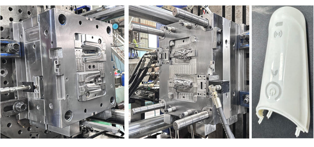
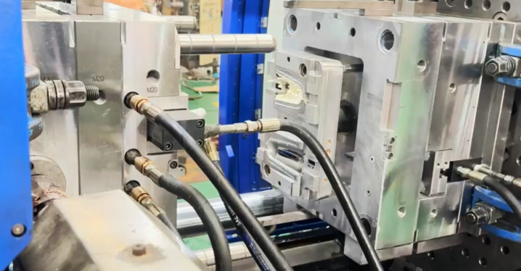
At TONGDA LINK facility we run a rotary-axis two-shot machine with 470T total clamping force, 820×800 mm tie-bar spacing and 780 mm mold opening stroke, with core-back capability. That defines our in-house sweet spot: small to medium two-color parts where the color boundary and bond line must be held tightly — buttons, caps, bezels, handles, trim accents.
For molds whose size or tonnage requirement exceeds this envelope, we arrange T1 sampling at a partner plant with a matched two-shot machine, then return the mold to our shop for correction and validation. The tool is built to our standard in both cases, so the DFM rules in this guide apply regardless of where the first shot is made.
Being clear about which machine the mold will run on saves everyone a wasted quotation cycle.
Get a Process Recommendation for a Plastic Part
Not sure whether rotary-axis or core-back suits your geometry? Tell us the part size and annual volume — we’ll recommend the route and adjust the design rules accordingly.
Foundational Principle: The Substrate Is the Core
In any 2K part, the first injected material is the substrate (base material). It forms the structural backbone and must be rigid enough to survive the pressure and temperature of the second injection without warping or deforming.
The substrate geometry dictates nearly everything else:
- It defines where the bond line or color break sits.
- It constrains where gates can be placed in both shots.
- It determines how the part cools and whether it warps before the second shot even starts.
Neglecting substrate design is the single most common reason for failure in 2K molding.
Wall Thickness Management
Keep both shots uniform. When some areas cool more slowly than others, differential shrinkage creates internal stress, sink marks, warpage, or cracks.
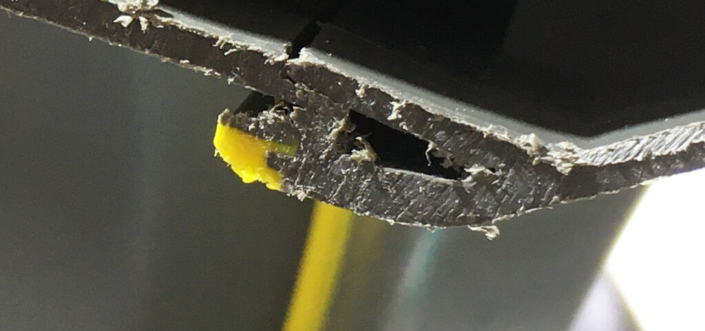
Transition gradually. Where thickness must change, use smooth fillets or tapers at a minimum 3:1 ratio. Sharp steps become stress concentrators and failure points.
Overmold thickness rule. As a guideline, the overmold layer should be 40–60% of the substrate thickness — typically 1.5–2.0 mm for TPE/TPU. A bulky overmold pushes hard on the substrate during injection and shrinks enough to warp the assembly. Below ~1.0 mm you risk short shots and weak bonding.
Use ribs, not mass. Ribs at 50–60% of nominal wall give stiffness without the sink. Core out thick sections.
Draft Angles — and Why First-Shot Retention Is a Separate Problem
A draft is required for both the substrate and the finished overmolded part:
- Smooth surfaces: minimum 0.5–1°
- Light texture: minimum 3°
- Heavy texture (leather grain): 5° or more
First-shot retention is not solved by draft. After the first injection, the part must stay on the moving (core) side during mold rotation. This is achieved with retention features — small undercuts, locking pins, or a deliberately asymmetric draft scheme — not by reducing draft. Insufficient retention causes the part to hang on the cavity side, and the rotation sequence fails before the second shot ever happens. This is one of the most frequent first-trial failures in 2K tools.
Designing for a Strong Bond Between Materials
Chemical Adhesion
Chemical bonding occurs when compatible polymers fuse at the molecular level. To maximize it:
- Maximize contact area at the interface.
- Ensure the second shot’s melt temperature is high enough to briefly re-melt the substrate surface layer for molecular interdiffusion.
- Choose materials whose processing windows overlap — amorphous/semi-crystalline mismatches need extensive validation.
Mechanical Interlocks
Where chemical compatibility is limited, add geometry:
- Grooves/channels: recessed channels ≥0.5 mm deep, 1–2 mm wide.
- Through-holes: the overmold flows through and locks on both sides like a plastic rivet.
- Undercuts/ledges: the overmold flows under and is trapped when solidified.
- Texture: light-to-medium texture on the bonding surface increases area and provides micro-undercuts.
Shut-Off Design
The shut-off is where steel meets steel to contain the melt and define the overmold edge. Design a clear step or groove (≥0.3 mm deep) at the overmold boundary to give the mold a sharp sealing edge. Flash at the boundary is most often a shut-off or wear issue rather than simply insufficient clamping force.
Same Material, Two Colors: A Different Set of Rules
Not all 2K molding involves two different polymers. A significant share of applications uses the same resin in two colors — two-tone buttons, caps, bezels, and handles where the goal is purely cosmetic: a clean, permanent color break without paint, film, or secondary assembly.
Here is the key point: when both shots are the same polymer family, the bonding problem essentially disappears — and the difficulty moves elsewhere.
The Bond Is No Longer the Risk
With identical base resin, the interface fuses into a near-monolithic structure. There is no chemical compatibility question, no shrinkage mismatch to balance, and essentially no long-term edge lifting after thermal cycling. You can skip the grooves, through-holes, and undercuts that dissimilar-material overmolding requires — which simplifies the tool and reduces cosmetic risk on the visible surface.
But this only holds if three conditions are met:
- Same polymer family, verified by grade, not by trade name. “Both are PC/ABS” is not enough — we check actual grade datasheets.
- Melt flow rates within a reasonable range. Too wide an MFI gap produces flow hesitation, splay, or a weak fusion layer at the color boundary.
- Second-shot temperature in the right window — high enough to re-fuse the first-shot surface, not so high as to degrade the existing skin.
Fail any of these and you will see delamination even though the materials are “the same.” It happens more often than expected.
Where the Difficulty Moves To
- The color boundary becomes the critical dimension. Flow-front position in the second shot typically varies shot to shot. On a large visible flat that variation is immediately obvious. Rule: never let a color break cross a large flat. Place it at a natural feature line, a sharp edge, or a dedicated decorative groove (0.3–0.5 mm deep) that absorbs the variation. In practice we treat the color boundary as a cosmetic datum and dimension from it.
- Shut-off edges wear faster than in dissimilar-material 2K. Steel sealing against steel with the same polymer flowing repeatedly across the same line is prone to galling. Flash at the color boundary is most often mold wear, not clamping force. Hardened inserts at shut-off lines in high-wear zones, on a defined inspection interval, are cheaper than a mid-production polish-and-repair.
- Gate vestige becomes a cosmetic defect. A gate mark in the first shot shows as a color blemish in the finished part. Either gate through the second-shot area so the mark is covered by the contrasting color, or use valve gates with pinpoint vestige in non-visible zones. Hot runner groups must be controlled independently so the two colors cannot migrate into each other at the nozzle tip during standby.
- Startup and color-change scrap is a real cost item. Every color change burns material until the screw and hot runner are fully purged. And because the two colors cannot be mixed, regrind must be segregated into two streams. Factories that forget this consistently under-quote same-material two-color jobs.
The Upside Worth Designing For
Matched shrinkage is the single biggest advantage. Because both shots contract at essentially the same rate, same-material two-color parts warp far less than dissimilar pairs, hold tighter positional tolerances across the boundary, and survive repeated thermal cycling without edge lifting. That makes thinner walls and larger flats viable — for two-tone trim and caps, it is often the simplest route to a clean, assembly-free finish.
Recent Examples from TONGDA LINK Shop
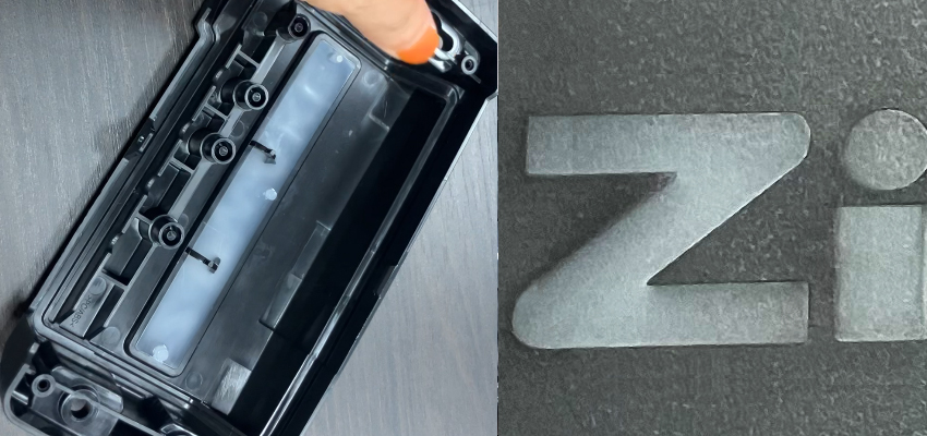
- Automotive auto start/stop disable button, PC/ABS, same material two color. Primary concerns were color bleed at the shut-off and waviness along the color boundary. Resolved within 2–3 sampling rounds (T1–T3); first article passed full dimensional inspection with the color boundary within drawing tolerance.
- Consumer electronics outer cover, PC/ABS, same material two color. Similar boundary-control issues, resolved at sampling; first article passed full dimensional inspection.
- Shampoo closure lid, ABS, same material two color. A packaging application where the color break had to align with a molded logo band — gate position and shut-off layout were the deciding factors.
- For comparison, a cosmetics applicator handle in ABS + TPE (dissimilar material) required mechanical interlocks and a verified hardness match — a completely different checklist from the three jobs above.
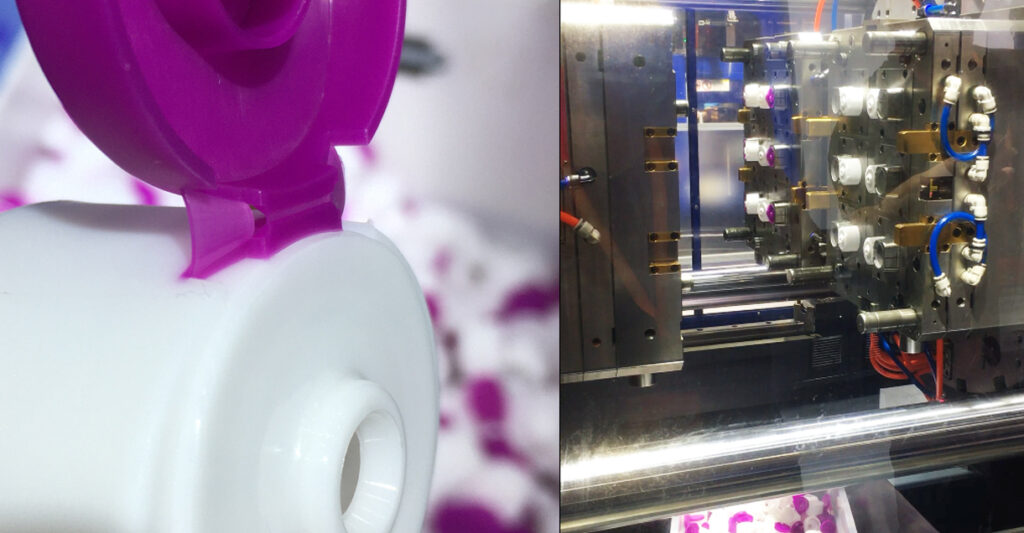
These are representative of the work we handle routinely. As a planning guide, we recommend allowing ±0.1–0.3 mm on the color/material boundary position at the design stage; on small, well-constrained parts such as buttons and caps we routinely hold tighter than that once the tool layout is locked. Final targets are confirmed per part during DFM.
Send TONGDA LINK Drawing for a Free DFM Review
Share a STEP or PDF file plus annual volume. We’ll come back within 48 hours with boundary tolerance, gate strategy, retention features, and any resin-compatibility concerns.
Gate Placement Strategy
Substrate gates: place in non-visible or non-critical areas, preferably in the thickest section for complete fill.
Overmold/second-shot gates: never gate directly onto a finished substrate surface — the high-pressure stream can erode or mark it. Route the flow to sweep smoothly across the substrate.
Avoid gate-to-gate alignment: the second-shot gate should not align with the first-shot gate, to prevent material contamination and flow interference.
For two-color parts: position the gate so flow crosses the bond line or color boundary perpendicular to it, increasing wetting pressure and boundary definition. Parallel flow along the interface is a common cause of weak bonds and ragged color breaks.
Common Mistakes and Solutions
| # | Mistake | Symptom | Fix |
|---|---|---|---|
| 1 | Uneven wall thickness | Sink marks, warpage, differential shrinkage | Uniform walls; ribs at 50–60% of nominal wall; core out thick sections |
| 2 | Incompatible material pairing | Delamination, peeling, low bond strength | Verify chemical compatibility before tooling; common pairs: ABS+TPE, PC+TPU, PP+TPE (grade-specific) |
| 3 | No first-shot retention features | Part sticks to cavity side, rotation sequence fails | Add undercuts/locking pins; check draft asymmetry |
| 4 | Insufficient bond surface area | Overmold lifts under stress | Maximize contact area; add grooves, through-holes, undercuts; texture the bonding surface |
| 5 | Shrinkage mismatch ignored | Warpage, edge lifting after thermal cycling | Match shrinkage; balance thickness ratios; confirm with moldflow analysis |
| 6 | Weak shut-off / worn inserts | Flash at the overmold or color boundary | Add step or accent groove ≥0.3 mm; hardened inserts; inspection interval |
| 7 | Sharp internal corners at the bond line | Crack initiation, fatigue failure | Radii ≥0.5 mm at all internal corners where the two materials meet |
| 8 | Color boundary on a large flat | Visible waviness / jagged color break | Move boundary to a feature line or add a 0.3–0.5 mm decorative groove |
| 9 | Gate vestige in the visible color | Blemish at the gate | Gate through the second-shot area or use pinpoint valve gates |
| 10 | Regrind streams mixed | Color contamination, inconsistent appearance | Segregate regrind by color from day one |
Material Compatibility Quick Reference
| Substrate | Compatible Overmold | Bond Approach | Typical Application |
|---|---|---|---|
| ABS | TPE, TPU | Chemical + mechanical | Automotive trim, tool handles |
| PC | TPU, silicone | Chemical + mechanical | Electronic housings, medical devices |
| PP | TPE (PP-formulated grades) | Mechanical strongly recommended | Consumer goods, closures |
| PA (Nylon) | TPU, TPE | Chemical + mechanical | Under-hood, industrial |
| PBT | TPE | Mechanical | Electrical connectors, seals |
| Same resin, two colors | — | Fusion (automatic) | Two-tone buttons, caps, bezels, handles |
Note: “compatible” is a grade-level property, not a resin-family property. Always confirm with the supplier’s bonding data for the exact grades you plan to run.
Request a Free 2K DFM Review
FAQ
A: The tool structure (rotary plate or core-back) can, but the shut-off layout, gate strategy, and venting are usually optimized for one case. If you may switch later, tell us during DFM so we design the shut-offs and hot runner groups with that flexibility in mind.
A: For molds and tooling, most customers accept ISO 9001 plus a second-party audit. For production parts supplying OEM assembly lines, IATF 16949 is typically required of the molder. We are ISO 9001 certified and support customers’ PPAP submissions with full dimensional reports, material certificates, and archived first-article records. Ask us about your program’s requirements.
TONGDA LINK Quality Control
A: As a starting point at the design stage, allow ±0.1–0.3 mm on the boundary position. On small, well-constrained two-color parts (buttons, caps, bezels) we routinely achieve tighter control once the tool layout and gate strategy are fixed. The final target depends on part size, geometry, resin, and whether a rotary-axis or core-back route is used — we confirm a realistic number during DFM and hold it on the first-article report, archived with the mold record.
A: Lead time depends on complexity, the number of shut-off lines, and whether mechanical interlocks or textured surfaces are involved. Share your 3D file and target timeline and we’ll come back with a realistic schedule.
Talk to TONGDA LINK 2K Mold Engineer?
No standard answers — tell us your part, material and volume, and we’ll tell you the process, the tolerance we can hold, and a realistic lead time.